
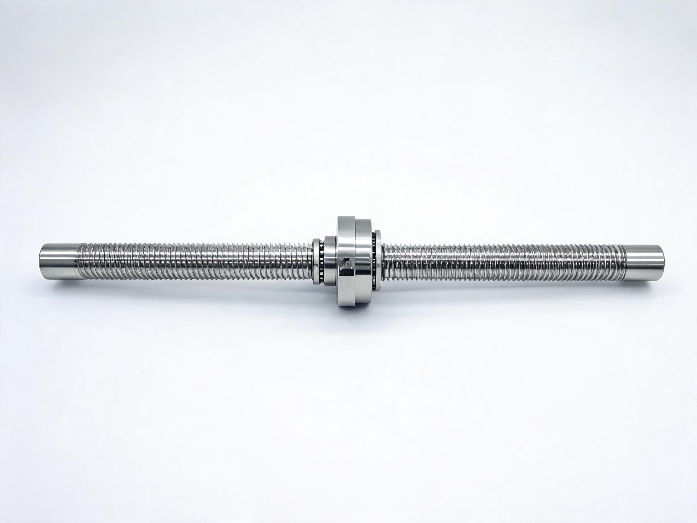
A practical selection guide that frames ball screw sizing by machine class, using three stocked rolled models (SFU1605, SFU2510, SFU3205) and their load, stiffness and lead trade-offs. It explains how shaft diameter, lead and nut capacity interact so buyers can specify the right screw for a desktop router, a mid-size gantry or a machining center axis.
Ball screw sizing for a CNC machine starts with one question: which axis are you building, and what does it actually carry? Shaft diameter decides stiffness, lead decides speed and resolution, and nut capacity decides whether the screw survives the load. Below we compare three stocked rolled models on the same basis so the trade-offs are visible side by side.
Key takeaways
- Desktop routers, laser engravers and 3D printer axes generally take a 16 mm screw: the SFU1605 with a 5 mm lead gives fine resolution for light, short travel.
- Mid-size router X/Y axes, plasma tables and woodworking gantries fit the SFU2510: 25 mm shaft, 10 mm lead, 17.2 kN dynamic load, standard lengths up to 3000 mm.
- VMC feed axes need the SFU3205: 32 mm shaft and a 5 mm lead, with about 2.5x the bending stiffness of the SFU2510.
- All three are C7 (ISO 3408) rolled screws at ±0.05 mm/300 mm. If an axis needs tighter than ±0.01 mm positioning, choose a ground series (SFE) instead.
- What sizing by machine class actually means
- The three stocked models compared
- Shaft diameter and stiffness
- Lead and the resolution/speed trade-off
- Matching each model to an axis
- When C7 is not enough
What sizing by machine class actually means
Buyers searching for a ball screw for CNC equipment usually start from a machine class rather than a number. A desktop router, a mid-size gantry and a machining center differ in three ways that drive screw choice: the moving mass the axis has to accelerate, the travel length the screw must span, and the positioning tolerance at the tool. These are the same conditions we use below to place each stocked model.
The sizing logic is that shaft diameter carries bending and buckling load over length, while lead converts motor rotation into linear travel. Selection is not about picking the biggest screw; it is about matching both values to the axis so the screw is stiff enough for its span without overbuilding the drive.
The three stocked models compared
The three models below are compared on the same basis: rolled C7 (ISO 3408) accuracy grade, GCr15 chrome steel, induction hardened to HRC 58-62, and identical lead accuracy of ±0.05 mm/300 mm. The differences are geometry and capacity.
| Model | Shaft | Lead | Dynamic load (single nut) | Static load | Standard lengths | Support blocks | Typical axis class |
|---|---|---|---|---|---|---|---|
| SFU1605 | 16 mm | 5 mm | 6.8 kN | confirm against the datasheet | 300-1500 mm | confirm against the datasheet | Desktop CNC routers, laser engravers, 3D printer axes |
| SFU2510 | 25 mm | 10 mm | 17.2 kN | 26.5 kN | 300-3000 mm | BK25 / BF25 | Mid-size CNC router X/Y axes, plasma tables, woodworking gantries |
| SFU3205 | 32 mm | 5 mm | 22.5 kN | 34.8 kN | 500-4000 mm | BK32 / BF32 | VMC feed axes |
Figures are as listed for the stocked models. Confirm nut configuration, preload and end-machining against the datasheet before ordering.
Shaft diameter and stiffness
Bending stiffness rises sharply with shaft diameter. Moving from the 25 mm SFU2510 to the 32 mm SFU3205 gives about 2.5x the bending stiffness. That matters on a machining center feed axis, where the screw spans a longer travel and the cutting load is carried into the screw through the nut. A stiffer shaft resists deflection and keeps the nut load path closer to design intent over that span.
The 16 mm SFU1605 is a light-duty shaft. On a short desktop axis with small moving mass, it is the appropriate size; asking a 16 mm screw to span the travel of a full machining center would load it beyond its class. Diameter, not lead, is the first decision to make because it sets the mechanical ceiling for the axis.
Lead and the resolution/speed trade-off
Lead is the linear distance the nut travels per revolution. The SFU1605 and SFU3205 both use a 5 mm lead; the SFU2510 uses 10 mm. The practical effect, at a given motor speed, is that the 10 mm lead moves twice as far per revolution as the 5 mm lead.
- A shorter lead gives finer linear resolution per motor step or encoder count, which suits axes where positioning and fine feed matter more than rapid traverse.
- A longer lead moves the axis faster for the same motor speed, which suits router X/Y axes covering long travel quickly.
Note that resolution and accuracy are separate properties. Lead determines how much travel one revolution produces; the C7 grade sets the lead accuracy at ±0.05 mm/300 mm. A finer lead does not by itself tighten that accuracy figure. Buyers should treat lead as a speed/resolution choice and grade as the accuracy statement.
Matching each model to an axis
Desktop CNC routers, laser engravers and 3D printer axes: SFU1605
The 16 mm shaft, 5 mm lead SFU1605 is sized for short travel and modest moving mass. Its 6.8 kN dynamic load suits the light axes these machines carry, and standard lengths from 300 to 1500 mm cover typical desktop footprints. The fine 5 mm lead fits axes where positioning detail matters. It is available within the SFU series rolled ball screw assembly range.
Mid-size CNC router X/Y axes, plasma tables, woodworking gantries: SFU2510
The SFU2510 rolled ball screw assembly with flange nut is the general-purpose mid-size choice. The 25 mm shaft carries more bending load than the 16 mm, the 10 mm lead gives faster traverse for gantry work, and the 17.2 kN dynamic / 26.5 kN static capacity covers heavier moving carriages. Standard lengths up to 3000 mm match mid-size router spans, and BK25/BF25 blocks are the matching end supports.
VMC feed axes: SFU3205
The SFU3205 heavy-duty rolled ball screw for CNC machining centers is the stiffest of the three. The 32 mm shaft delivers about 2.5x the bending stiffness of the SFU2510, the 22.5 kN dynamic / 34.8 kN static load handles machining feed loads, and the 5 mm lead gives fine feed resolution for a machining center axis. Standard lengths run 500-4000 mm with BK32/BF32 blocks.
When C7 is not enough
All three models are C7 (ISO 3408) with lead accuracy of ±0.05 mm/300 mm. That is a rolled-screw grade and covers a large share of router, plasma and engraver axes. For an axis that must hold tighter than ±0.01 mm positioning, a ground series (SFE) is the better fit, because the rolled grade's accuracy statement will not meet it.
The decision rule is simple: define the required positioning tolerance first, then choose the grade that meets it, then size the shaft and lead to the axis. Choosing a larger rolled screw will not substitute for a ground screw on an axis with a tolerance tighter than the grade allows.
A short specification checklist
To get a usable quote, state the following facts for each axis rather than a model number alone:
- Axis class and machine type (desktop router, mid-size gantry, VMC feed).
- Travel length and required screw length within the standard ranges above.
- Estimated moving mass and the load the nut must carry; compare to dynamic and static ratings.
- Required positioning tolerance, so the accuracy grade is set before sizing.
- Preferred lead based on speed versus resolution priority.
- End support blocks (BK25/BF25 or BK32/BF32) and end-machining drawing.
With those inputs, the choice between the three models becomes a check against published figures rather than guesswork. Where a value is unknown, mark it as open and confirm it against the datasheet with the supplier before committing to a drawing.
Next step
If you are sizing a desktop axis, review the SFU1605 within the SFU series; for mid-size gantries, start from the SFU2510; for machining center feed axes, use the SFU3205 page. Take your travel, load and tolerance figures from the checklist above to each product page and confirm the final nut configuration and end-machining against the datasheet.