
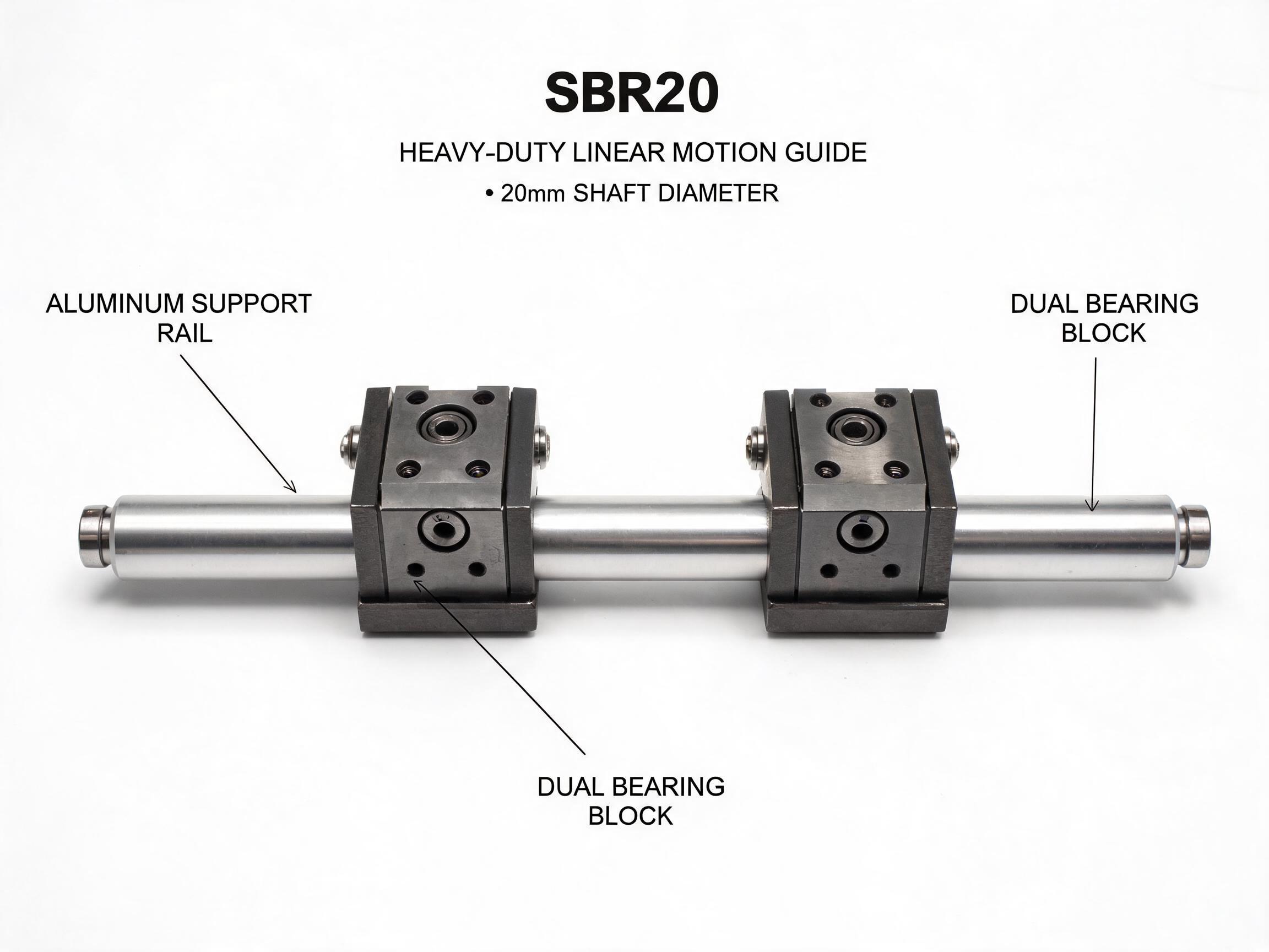
When an axis outgrows its current linear bearing, the answer is not always a jump to a much larger rail. This article explains four layout strategies — dual blocks, a synchronized dual-shaft carriage, extended-length sleeves and a careful rail step-up — with the load figures each one actually delivers, plus the load-direction, static-margin and block-spacing checks that decide which fits.
Your axis needs more capacity than the single-block bearing on it now carries — but the jump to the next rail size adds height, mass and cost to everything around it. There are four ways to raise capacity first. This guide gives the numbers each one delivers and explains when a layout change beats a size change.
Key takeaways
- Dual blocks on one rail roughly double axis capacity and cut per-block stress.
- A synchronized two-shaft carriage doubles moment resistance for cantilevered loads.
- Extended-length sleeves add ball contact without changing the housing footprint.
- Stepping up rail size is the largest single gain — and the largest rebuild.
The decision to make for linear bearing heavy load applications is whether the extra capacity is needed in a straight push, in a moment, or in both. That answer points to a different fix in each case. A carriage that only carries a vertical load and a carriage that hangs a load out on a cantilever do not fail the same way, and they do not need the same upgrade.
First, identify which load direction is actually limiting
Catalog ratings are usually quoted as a dynamic load C and a static load C0 for a vertical, centered load. They do not describe how the same bearing behaves when the load hangs off the side of the carriage, or when a moment tries to rotate the carriage around the rail. Before choosing an upgrade, separate three load paths on your axis:
- Radial load — force pushing the carriage down or up against the shaft or rail. This is the path the headline load rating describes.
- Moment load — load offset from the carriage center, such as a tool head on a bracket. This grows with the distance to the load, not just with its mass.
- Side load — force across the rail. On round-shaft units this shifts the internal ball loading and is not covered by a single radial figure.
If the limiting case is a moment, adding blocks at a wider spacing is usually a more efficient answer than a bigger bearing, because spacing directly attacks the moment arm. If the limit is pure radial force with a centered load, adding bearing contact area is the direct path.
Option 1: two bearing blocks per rail
The simplest capacity increase is to put two blocks on the same rail, separated along the travel direction, and bolt a single carriage plate across them. On the SBR20 heavy-duty linear motion guide unit with dual bearing blocks, a 20 mm shaft carries 11.2 kN dynamic and 17.5 kN static per block. Two blocks per rail therefore give 22.4 kN dynamic per axis.
The second benefit matters more than the arithmetic. Manufacturer data for this dual-block arrangement states that the two blocks halve per-block stress and extend travel life about 80% compared with a single block under equivalent load. The load is shared, so each ball row sees less contact stress; and the block spacing resists rotation of the carriage plate about the rail, which reduces the moment that either block has to carry alone.
Block spacing is the parameter to set deliberately. Place the two blocks as far apart as the stroke allows: the larger the center distance, the lower the moment each block sees from an offset load. A pair mounted close together behaves much like one longer block and gives back some of the moment benefit.
Check the static margin on the modified layout
Doubling the dynamic figure does not mean the static figure doubles the same way under every load direction. Use the static rating for the maximum force the axis could see — a crash, a fixture clamp, an operator leaning on the carriage — and keep a static margin suitable for your machine type. What margin is acceptable depends on the application and on the shock content of the cycle; confirm the required static safety factor with the datasheet or supplier rather than defaulting to one number.
Option 2: two shafts, one synchronized carriage
When the problem is a cantilevered load, a second shaft is often a better investment than a larger one. The TBR16 synchronized dual shaft linear motion guide system runs two parallel 16 mm shafts inside one carriage housing, so the load is taken across a wide base rather than through a single shaft centerline.
| Property | TBR16 synchronized dual-shaft carriage |
|---|---|
| Shaft diameter | 16 mm, two parallel shafts |
| Dynamic load | 15.6 kN (7.8 kN × 2) |
| Static load | 24.0 kN per carriage |
| Moment resistance | 2× versus a single-shaft SBR for cantilevered axes |
| Shaft center distance | 60 / 80 / 100 mm |
The 60/80/100 mm center-distance options let you match the housing width to the moment arm of your load. A long cantilever wants the widest spacing that the machine envelope can accept, because the resisting moment scales with the distance between the shaft centerlines. The synchronized housing also keeps both shafts loaded together, so the carriage cannot rock from one shaft to the other as a loosely coupled twin-rail layout can.
This is usually the right choice for gantry cross-axes, robotic end-effector travel and any axis where the tool center sits well off the carriage center.
Option 3: extended-length bearings with more balls
If the housing footprint must stay the same, an extended sleeve adds capacity inside the existing bore. An LMUU sealed extended sleeve carries 40% more balls than a standard LM bearing and drops into standard LM housings. For reference, the standard LM16UU is rated 1,580 N dynamic and 2,450 N static; the extended version adds contact through the extra ball rows while keeping the same mounting arrangement.
This option suits light-to-medium axes where the existing housing and shaft are already fixed and the required gain is modest. It is not a substitute for a rail-size change when the shaft itself is the limiting element — the shaft's own deflection under an offset load is unchanged by a longer sleeve. For any axis where shaft bending is a concern, calculate shaft deflection separately and confirm the allowable value with the datasheet or supplier.
Option 4: step up the rail size
When a layout change is not enough, a profile rail step-up delivers the largest single gain. The HGR45 heavy-duty large linear guideway rail is 45 mm wide by 38 mm high, and with an HGW45CA carriage it is rated 62.8 kN dynamic and 112 kN static per carriage. The rail is induction hardened to 58–62 HRC with a case depth of 2.0–2.5 mm.
That static figure — 112 kN from a single carriage — is the reason to treat this as a rebuild rather than a swap. A 45 mm profile rail changes mounting height, bolt pattern and the stiffness of the structure it bolts to. Plan the change at the frame level: the carriage mounting face moves up by the difference in rail and carriage height, and the frame's flatness and stiffness need to suit the larger rail. Surface preparation requirements for the mounting face should be confirmed with the datasheet or supplier before machining.
Comparing the four routes
| Route | Capacity it adds | Best fit | What changes |
|---|---|---|---|
| Dual blocks on one rail | 22.4 kN dynamic per axis on SBR20; per-block stress halved | Radial-dominated load, moderate moment | Rail length and carriage plate; block spacing |
| Synchronized dual shaft | 15.6 kN dynamic, 24.0 kN static; 2× moment resistance | Cantilevered or offset loads | Adds a second shaft and a wider housing |
| Extended sleeve | 40% more balls than standard LM | Tight footprint, modest gain | Bearing only; housing unchanged |
| Profile rail step-up | 62.8 kN dynamic, 112 kN static per carriage | Heavy radial and moment load together | Frame, mounting height, bolt pattern |
A practical order of operations
Start from the load case rather than the catalog page. Write down the maximum radial force, the offset distance from the carriage center to the load center, and whether the load can reverse direction during the cycle. Then:
- If the moment dominates, widen the support first — dual blocks with generous spacing, or a synchronized dual-shaft carriage on the widest center distance the envelope allows.
- If radial load dominates and the footprint is fixed, add contact area — an extended sleeve or a second block.
- If both are high, or the shaft or rail would deflect beyond the machine's accuracy requirement, step up the rail size and design the frame around it.
In every case, state the load direction and the moment arm in the request to your supplier, not just the required load figure. Two axes with the same radial load can need very different bearings if one carries it centered and the other on a 300 mm bracket. Confirm the final static margin, shaft deflection limit and mounting-face requirements with the datasheet or supplier before committing to hardware.
FAQ
Can I just add a second block to double my load rating?
The dynamic figure roughly doubles, and for the SBR20 dual-block unit two blocks per rail give 22.4 kN per axis from 11.2 kN per block. The static rating and the moment behavior still need checking for your specific load direction, and the two blocks must be spaced apart to get the full moment benefit.
When should I choose two shafts instead of a bigger single shaft?
When the load is cantilevered or offset from the carriage center. The TBR16 synchronized system gives 2× moment-load resistance versus a single-shaft SBR for cantilevered axes, with shaft center distances of 60, 80 or 100 mm. A bigger single shaft raises radial capacity but does not widen the resisting base.
Does an extended-length sleeve work in my existing housing?
An LMUU sealed extended sleeve carries 40% more balls than standard LM and is designed to drop into standard LM housings. It adds ball contact but does not change shaft stiffness, so calculate shaft deflection separately if your load is offset.
What load information should I give a supplier for a heavy-load axis?
Give the maximum radial force, the offset distance from carriage center to load center, the load direction or reversal, the required stroke and the allowable deflection. That set lets the supplier compare layout options rather than quote a single bearing size.