
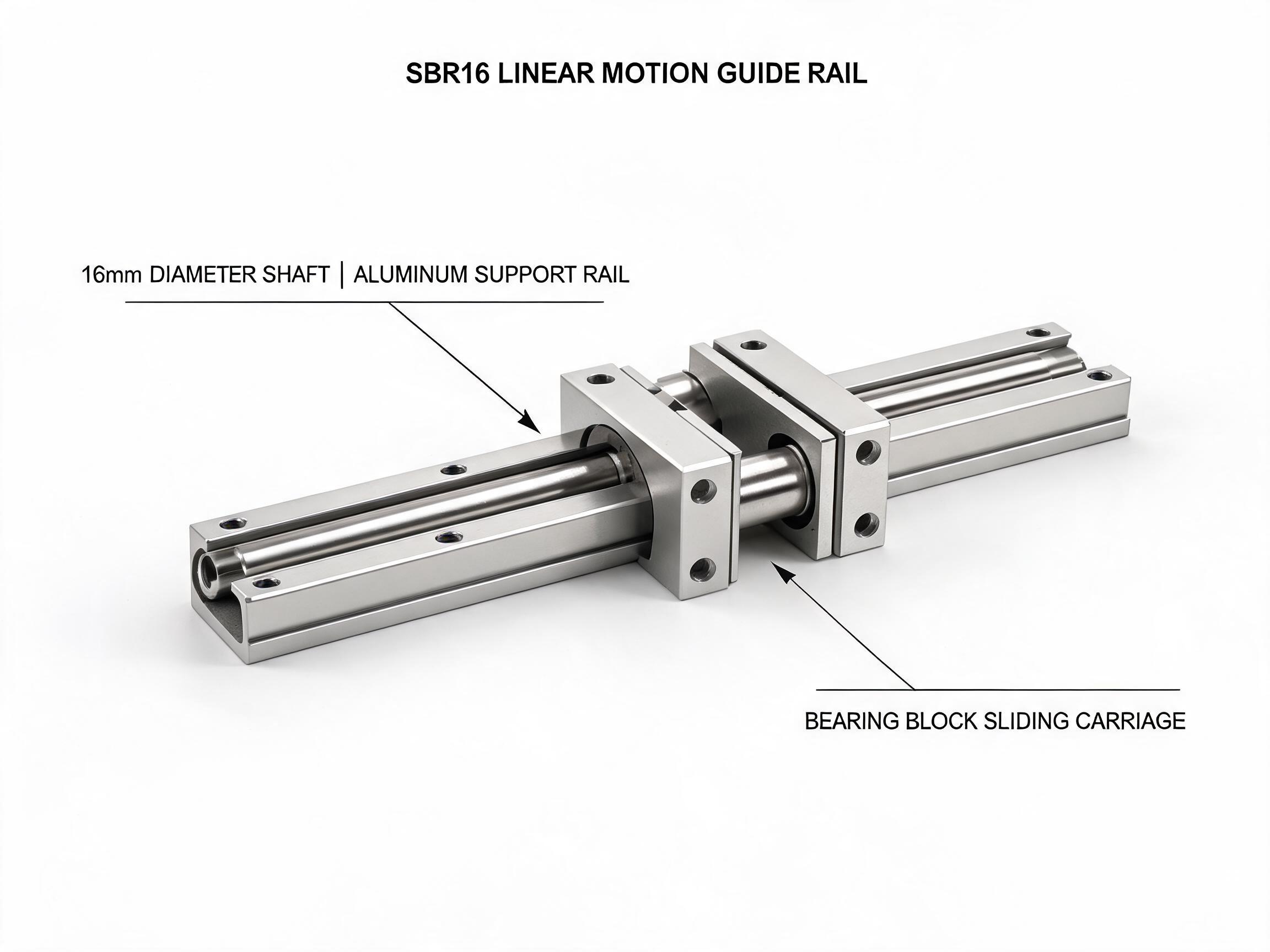
A long-stroke round-shaft axis fails or succeeds on shaft support, bearing spacing and alignment, not on the bearing alone. This article compares supported rail units, unsupported shafts and self-aligning pillow blocks, separates complete-unit from bare-bearing load ratings, and gives a layout checklist to run before ordering.
Long travel on round shafts changes the problem from “which bearing” to “how the shaft is held and how the bearings are spaced.” A carriage that runs smoothly on a bench can bind, rock or wear unevenly once the stroke is several times the bearing length, because shaft deflection and mounting misalignment become part of the geometry. The decisions below cover supported versus unsupported shafts, when pillow blocks earn their place, and the layout checks worth completing before a purchase order is issued.
Key takeaways
- Load ratings for a complete unit (with housing) and a bare bearing come from different test conditions and are not comparable — never use one to justify the other.
- Unsupported round shafts deflect under load; an aluminum support rail carries the shaft along its length and limits that deflection.
- Self-aligning pillow blocks absorb small mounting misalignment (rated at ±3° for the KH series), which matters over long spans.
- Fix span, shaft diameter, bearing spacing and end support in the drawing before ordering; do not choose bearings first and fit the structure afterwards.
Why long unsupported shafts deflect
A round shaft supported only at its two ends behaves as a beam. Under a carriage load applied between the supports, it bends, and the maximum deflection grows sharply as the span increases. On a short axis the movement is small enough that a standard bearing can follow it. On a long axis the shaft sags in the middle, the carriage tilts, and the bearing runs on a line that is no longer parallel to the shaft ends. The result is uneven contact, higher friction at mid-stroke, and a carriage that feels different at the centre of travel than at the ends.
Deflection is not the only variable. The mounting surface the shafts sit on also matters: if the two shafts are not parallel in both planes, or if the end supports sit at different heights, the carriage is forced into a wedge between them. Over a short stroke this can be taken up by clearance. Over a long stroke it converts into binding.
What a support rail changes
A supported shaft is a shaft carried on a continuous aluminum support rail, so the shaft is backed along its full length rather than only at the ends. The rail resists the bending that an unsupported shaft would otherwise accumulate, and the shaft-to-rail assembly becomes a stiffer beam for the same shaft diameter. This is the SBR16 linear motion guide rail unit arrangement: a 16 mm shaft on an aluminum support rail, with a dynamic load rating of 7.8 kN and a static load rating of 12.0 kN, MOQ 50.
The same family extends to larger sizes. The SBR20 unit is rated at 11.2 kN dynamic and 17.5 kN static per block — 22.4 kN per axis with its dual-block configuration — with available lengths up to 3000 mm and MOQ 30. Above that, the maximum length for a given series should be confirmed against the datasheet rather than assumed from a neighbouring size, because the support rail profile and shaft diameter both change with the series.
What the rail does not do is remove the need to check parallel alignment. A supported rail keeps the shaft straighter; it does not correct two rails that are mounted at an angle to each other. Alignment remains a separate task.
Complete unit versus bare bearing: keep the ratings apart
Catalog numbers are only useful when the test condition behind them is clear. A load figure quoted for a complete unit with housing describes the assembly, including the housing that carries and locates the bearing. A figure quoted for a bare bearing describes the bearing alone, before any housing is added. These are different calibers and must not be compared directly or substituted for one another in a load calculation.
| Product | Rating caliber | Listed load | Notes |
|---|---|---|---|
| SBR16 unit | Complete unit (shaft on aluminum support rail, with carriage block) | 7.8 kN dynamic; 12.0 kN static | 16 mm shaft; MOQ 50 |
| SBR20 unit | Complete unit (shaft on aluminum support rail, with carriage block) | 11.2 kN dynamic per block; 17.5 kN static per block; 22.4 kN per axis dynamic | Lengths up to 3000 mm; MOQ 30 |
| LMUU sealed extended-length bearing (LM16UU) | Bare bearing | 1580 N dynamic; 2450 N static | NBR seals listed at 95% dust reduction; −30 to 110 °C; MOQ 100 |
| KH series pillow block unit (KH16) | Complete unit (includes housing) | 980 N | Self-aligning ±3°; tool-free bearing replacement; MOQ 100 |
Extended-length sealed bearings such as the LMUU series are relevant to long-stroke axes because the longer bearing body spreads load over more shaft and resists tilting better than a short bearing. Sealing matters too: the NBR seals are listed at 95% dust reduction, and the operating range of the bare bearing is −30 to 110 °C. Those figures describe the bearing; they do not predict the temperature or contamination limits of the finished axis, which depend on the housing, lubrication and environment.
Bearing spacing along the stroke
Two bearings on one shaft act as a couple. Spacing them further apart increases resistance to carriage rotation, but it also increases the sensitivity to any misalignment between the two bearing positions. On a long-stroke axis the practical compromise is to space the bearings far enough to control tilt and close enough that both can be aligned to the same shaft line without preload.
A useful way to think about it: the carriage should not be able to rotate visibly when a load is applied at the end of its overhang. If it can, the spacing is too short for the overhang, regardless of the bearing load rating. If the carriage binds at the mid-stroke and frees up at the ends, the spacing is not the first suspect — check shaft deflection and rail parallelism first.
When to use self-aligning pillow blocks
A pillow block unit surrounds the shaft with a housing that can rotate slightly to follow the shaft. The KH16 unit is listed at ±3° self-alignment, with a complete-unit load of 980 N and tool-free bearing replacement, MOQ 100. The self-aligning feature is what makes pillow blocks useful on long strokes: where a rigid housing would fight a small mounting error, the pillow block absorbs it.
That tolerance is bounded. A ±3° rating covers mounting misalignment within that range; it is not a licence to mount rails out of parallel on the assumption the housing will compensate. Use pillow blocks where the structure makes small angular error likely — long frames, welded bases, assemblies that are aligned on site — and still align the rails to a reasonable standard. The same applies to bearing replacement: a tool-free swap shortens downtime, but a bearing replaced into a misaligned housing will wear the same way the original did.
Layout checks before ordering
Run these checks against the drawing, not against the catalogue page. Each one changes what should be ordered.
Span and shaft diameter
- Record the unsupported span between end supports and the supported length if a rail is used. These are different numbers and drive different deflection.
- Match shaft diameter to the load and span together. A larger shaft on a long span reduces deflection; the same shaft on a short span may be adequate.
- Confirm the maximum available length for the chosen series against the datasheet. SBR20 is listed up to 3000 mm; do not carry that figure across to other series without checking.
End supports and mounting surface
- Specify how each shaft end is held — end support block, rail end fixing, or a frame feature — and confirm the mounting surface is flat and continuous over the stroke.
- Check that both shafts sit at the same height and are parallel in plan and elevation. This is where long axes fail most often.
- Plan for adjustment at assembly. A design that can only be bolted down, not shimmed or trimmed, leaves no path to correct a small error.
Bearing choice and spacing
- State whether the load figure you are working from is a complete unit or a bare bearing, and keep the calculation in that caliber.
- Fix bearing spacing from the carriage overhang and the tilt you are willing to accept.
- Decide whether a rigid housing or a self-aligning pillow block suits the structure, and record the reason in the drawing notes.
Environment
- Sealing and temperature limits should be checked against the actual axis environment, not assumed from the bearing specification alone.
- Confirm lubrication access along the full stroke before the design is frozen.
Getting the order right
Long-stroke round-shaft axes are decided mostly by the structure around the bearing. Supported rail units limit shaft deflection, self-aligning pillow blocks tolerate small mounting error, and bearing spacing controls carriage tilt. The load ratings that guide the choice must stay within their own caliber: complete unit with housing on one side, bare bearing on the other, never mixed. Once span, shaft diameter, end support and bearing spacing are fixed on the drawing, the parts list follows from it rather than the other way round.