
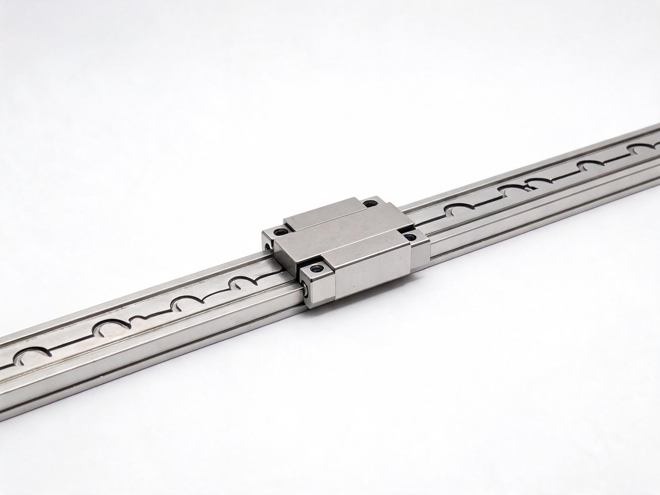
A practical selection guide for B2B buyers comparing single-axis linear slides, cross-axis (XY) tables, and aluminum profile gantry modules. Covers load capacity calculation, stroke selection, repeatability, rigidity, and application fit for automation equipment builders.
BUYER GUIDE
When you are building an automation rig, a pick-and-place station, or a custom CNC machine, the linear motion components you choose determine the machine's real performance. The problem: most suppliers list a dozen "series" with similar-looking photos, and the spec sheets use different measurement conventions. This guide gives you the actual selection criteria — how to compare single-axis slides, cross-axis (XY) tables, and aluminum profile modules — and how to calculate the load and stroke you actually need.
- Single-axis slides suit simple push/pull and vertical lift tasks; cross-axis tables handle XY positioning; aluminum profile modules are for gantry-style, multi-axis layouts.
- Load capacity is not a single number — you must compare at the same speed, duty cycle, and mounting orientation.
- Stroke length directly affects the module's overall length and rigidity. Longer strokes need wider profiles or dual-rail designs.
- Repeatability (±0.02 mm vs ±0.05 mm) is the spec that decides whether a module works for your process — not the top speed.
- Always request the supplier's load-life chart. If they cannot provide one, treat the catalog rating as unverified.
What Is a Linear Slide Module (linear slide module)?
A linear slide module is a ready-to-install motion unit that combines a guide rail, a carriage (slider), a drive mechanism (ball screw, lead screw, or timing belt), and a frame — usually extruded aluminum. The term "linear slide module" covers all three configurations discussed in this guide. The supplier pre-assembles and pre-loads the system, so you do not have to source rails, bearings, screws, and couplings separately and align them on-site.
For overseas buyers, the key advantage is time. A module arrives as a tested assembly. You mount it, wire the motor, and run. The selection question is which configuration fits your machine's motion pattern.
Single-Axis Slide: When One Direction Is Enough
A single-axis slide (single-axis slide) provides linear motion in one direction. It is the most common building block. Typical uses: pushing a part into a press, lifting a nozzle, moving a camera along a track, or feeding material step-by-step.
Strengths
- Simplest to integrate — one motor, one driver, one axis.
- Lowest cost per axis of travel.
- Compact: narrow profile options down to 45 mm width.
- Easiest to replace or service.
Limitations
- No lateral (Y) movement — you need a second axis for that.
- Long cantilevered loads cause moment forces that reduce effective load capacity.
- For vertical (Z) applications, you must account for gravity and brake requirements.
When to choose it
If your process requires movement along one line only, a single-axis slide is the right call. Common industries: packaging (push-off mechanisms), electronics assembly (screw driving), and inspection (line-scan camera travel).
Cross-Axis (XY) Table: Two Axes, One Compact Footprint
A cross-axis table stacks two single-axis slides perpendicularly — a bottom axis (X) and a top axis (Y) mounted on the carriage of the bottom one. The result is a compact XY positioning stage.
Strengths
- Complete XY motion in one package — no need to design and align two separate axes.
- Better rigidity than bolting two single-axis units together, because the frame is engineered as a system.
- Ideal for dispensing, soldering, vision inspection, and small-part assembly.
Limitations
- The top axis adds mass and height, which reduces the effective payload of the bottom axis.
- More complex to wire and program than a single axis.
- Limited travel range — typically 100 mm to 600 mm per axis in compact designs.
When to choose it
Choose a cross-axis table when your work area is small and you need precise point-to-point positioning in two directions. For example: a glue-dispensing head moving over a 300 mm x 300 mm work area, or a vision camera scanning a PCB panel.
Aluminum Profile Gantry Module: The Heavy-Duty Multi-Axis Solution
An aluminum profile module (aluminum profile module) is a structural frame — usually T-slot aluminum extrusions — combined with one or more linear slides to form a gantry. The frame spans the work area, and the slide(s) move along it. This is the configuration for large-format machines: CNC routers, laser cutters, large-format printers, and automated pick-and-place with wide reach.
Strengths
- Handles large travel lengths — 1 meter to 3+ meters without the deflection issues of a stacked XY table.
- High load capacity because the frame is bolted to the machine base, not carried by another axis.
- Modular: you can extend the frame, add a Z axis, or add a rotary axis later.
- Better stiffness-to-weight ratio than a stacked XY design for large spans.
Limitations
- Requires more engineering on your side — you design the frame, the axis mounting, and the cable management.
- Higher total cost when you count the frame, brackets, and assembly time.
- Longer lead time for a custom frame.
When to choose it
Choose a gantry module when your work area exceeds roughly 600 mm in any direction, or when you need to carry a heavy tool head (spindle, dispenser, or gripper) across a wide span. It is also the right choice when you need to integrate multiple tools on one bridge.
Direct Comparison: Which Configuration for Which Job?
| Selection Factor | Single-Axis Slide | Cross-Axis (XY) Table | Aluminum Profile Gantry |
|---|---|---|---|
| Typical travel range | 50 – 1500 mm | 100 – 600 mm per axis | 500 – 3000+ mm |
| Max load capacity (typical) | 5 – 200 kg (horizontal) | 5 – 50 kg on top axis | 20 – 500+ kg |
| Repeatability | ±0.01 – ±0.05 mm (ball screw) | ±0.01 – ±0.03 mm | ±0.02 – ±0.08 mm |
| Rigidity | Good for short spans | Good for compact areas | Best for large spans |
| Integration effort | Low | Medium | High |
| Typical cost per axis | Lowest | Medium | Highest |
| Best for | Push, lift, single-line feed | Dispensing, soldering, inspection | CNC, laser, large pick-and-place |
Load Calculation: The Practical Method
Load capacity is the most misunderstood spec. A module rated for 50 kg horizontal may only carry 15 kg when mounted vertically, or when the load is offset from the carriage center. Here is the calculation method we use when quoting modules for customers.
Step 1: Define the actual load condition
List three numbers: the mass of the payload (kg), the distance from the carriage center to the load center (mm), and the mounting orientation (horizontal, vertical, or inverted). The offset distance matters because it creates a moment (torque) on the carriage.
Step 2: Calculate the moment
Moment (N·m) = mass (kg) × 9.81 × offset distance (m). For example, a 10 kg load centered 100 mm from the carriage creates a moment of 10 × 9.81 × 0.1 = 9.81 N·m. Compare this against the module's allowable moment ratings — most suppliers list values for pitch, roll, and yaw.
Step 3: Apply the duty cycle factor
If your application runs continuously (more than 60% of the time), derate the catalog load by 30–40%. If it is intermittent (start-stop cycles), derate by 15–20%. Heat is the enemy of ball screws and linear guides — continuous operation raises temperature and shortens life.
Step 4: Check the life rating
Ask the supplier for the L10 life (the distance that 90% of a sample group will survive). A typical ball screw module is rated for 10,000–20,000 km of travel at a specified load. If your machine runs 8 hours/day at 0.5 m/s, that is roughly 14,400 m/day — about 2 years at the rated load. If you exceed the rated load, life drops by the cube of the load ratio. Overload by 20% and life drops to roughly 58%.
Stroke Selection: More Is Not Always Better
Longer stroke sounds safer, but it comes with trade-offs. As stroke increases, the module's overall length grows, the unsupported span increases, and the dynamic rigidity drops. A 1000 mm stroke module with a 20 mm rail will flex more than a 500 mm module with the same rail.
Practical guidance:
- Measure the actual travel your process needs, then add 10–15% for safety and end-of-stroke deceleration.
- For strokes above 800 mm, request a wider profile or a dual-rail design.
- For vertical (Z) axes, add a brake or counterbalance if the load exceeds 20 kg — a powered-off axis with a heavy load will drop.
- For gantry designs, the span between the two side rails determines the frame profile size. A 1200 mm span typically needs a 60×60 mm or larger profile to keep deflection under 0.1 mm.
Drive Type: Ball Screw vs. Timing Belt
Within each configuration, you also choose the drive mechanism. This is often the deciding factor for price and performance.
| Drive Type | Repeatability | Max Speed | Thrust | Best For |
|---|---|---|---|---|
| Ball screw | ±0.01 – ±0.03 mm | 0.5 – 1 m/s | High | Precision positioning, heavy loads |
| Lead screw | ±0.05 – ±0.1 mm | 0.1 – 0.3 m/s | Medium | Low-cost, low-speed, light loads |
| Timing belt | ±0.05 – ±0.1 mm | 2 – 5 m/s | Low-Medium | High-speed transfer, light payloads |
If your process requires better than ±0.05 mm repeatability, you need a ball screw drive. If you are moving light parts fast (like a pick-and-place transfer), a belt drive is the economical choice. If cost is the top priority and speed is below 0.3 m/s, a lead screw module is acceptable.
Common Mistakes in Module Selection
- Ignoring the moment load. An offset load is the #1 cause of premature wear. Always calculate the moment, not just the mass.
- Choosing stroke first, then load. These interact. A long stroke reduces the effective load capacity. Decide both together.
- Overspecifying repeatability. ±0.01 mm costs significantly more than ±0.05 mm. If your process tolerates ±0.05 mm, do not pay for the tighter spec.
- Forgetting the motor and driver cost. The module price is often quoted without the stepper/servo motor, driver, and cabling. These can add 30–50% to the total axis cost.
- Not asking for the load-life curve. If a supplier cannot provide one, their load rating may be a static number, not a dynamic one. Ask for it in the RFQ.
How to Write an RFQ That Gets Accurate Quotes
When you contact a supplier, include these seven items to get a comparable quote:
- Configuration: single-axis, XY table, or gantry.
- Travel (stroke) per axis in mm.
- Payload mass in kg and load offset from carriage center in mm.
- Mounting orientation: horizontal, vertical, or inverted.
- Required repeatability in mm.
- Maximum speed in m/s and duty cycle (e.g., 20 cycles/min, 8 h/day).
- Motor preference: stepper, servo, or no motor (customer-provided).
With these details, a supplier can size the rail, screw, and motor correctly. Without them, you will receive a quote based on assumptions — and the delivered module may not match your machine's real needs.
FAQ
Can I use a single-axis slide for vertical lifting?
Yes, but with precautions. Add a brake to prevent the carriage from dropping when power is off. Derate the load by at least 50% compared to horizontal use. For loads above 30 kg, consider a counterweight or a ball screw with a larger lead.
What is the difference between a cross-axis table and two single-axis slides bolted together?
A purpose-built XY table has a machined base that maintains perpendicularity between the two axes. Bolting two slides together requires you to align them perfectly, which is difficult and time-consuming. The XY table also has better overall rigidity because the frame is designed as one unit.
How do I know if my gantry frame is rigid enough?
Calculate the deflection of the span under the worst-case load. For a simply supported beam, deflection = (F × L³) / (48 × E × I), where F is the load in N, L is the span in mm, E is the elastic modulus of aluminum (~70,000 N/mm²), and I is the moment of inertia of the profile cross-section. Keep deflection under 0.1 mm for precision work.
What is the typical lead time for a custom linear slide module?
Standard modules are usually in stock or ship within 7–15 days. Custom strokes, special motors, or gantry frames typically take 15–30 days depending on the configuration. Confirm the lead time in your RFQ.
Next Steps
Start with your machine's motion pattern, not the product catalog. Define the travel, load, and repeatability you need, then match those numbers against the three configurations in this guide. If you are still unsure, send us your application details — the load, stroke, orientation, and cycle time — and we will recommend a configuration with a load-life calculation. For standard modules, we can provide a quote within 48 hours.