
A buyer's guide to selecting linear motion components for FDM 3D printers, mapping each axis to the right hardware family: low-profile slide units for space-constrained beds, miniature profile rails for precision carriages, and C7 ball screws for Z-axis drive. Includes a height-budget and load checklist.
Buyer's Guide
3D Printer Linear Motion: Rails, Bearings and Screws
When you source motion components for an FDM printer, the decision is not simply "rail or bearing." Each axis carries different loads, speed requirements, and space constraints. A single printer may use three different component families: a low-profile slide unit under the bed, a miniature profile rail on the carriage, and a rolled ball screw on the Z-axis. This guide maps those choices axis by axis, with a height-budget and load checklist to help you specify the right hardware for desktop equipment builds.
- Height-constrained beds benefit from low-profile slide units with integrated shaft and support rail.
- Precision carriages are best served by miniature profile rails with Gothic-arch circuitry and P5 raceway grinding.
- Z-axis drive typically requires a C7 rolled ball screw with 5 mm lead for sub-0.1 mm repeatability.
- Always calculate total stack height and dynamic load per axis before finalizing component dimensions.
Mapping printer axes to component families
Desktop FDM printers typically have three linear axes: X (carriage), Y (bed or gantry), and Z (vertical). Each presents a different combination of constraints. The table below summarizes the typical mapping, though final selection depends on your specific load and height budget.
| Axis | Typical constraint | Recommended component family | Example product |
|---|---|---|---|
| X (carriage) | Low moving mass, high precision, moderate speed | Miniature profile rail with compact carriage | EGH15CA miniature guideway |
| Y (bed) | Space under bed, moderate load, height limit | Low-profile slide unit with integrated shaft support | SBS16 low-profile slide unit |
| Z (vertical) | Holding load, fine lead, repeatability under 0.1 mm | C7 rolled ball screw | SFU1605 C7 ball screw |
This mapping is not absolute. Some printers use linear guides on all axes, while others prefer ball screws on X or Y. The key is to match the component's load capacity, height, and accuracy to the axis's actual duty.
Height-budget checklist
In desktop printers, vertical space is often the tightest constraint. Before selecting any linear component, build a height budget that accounts for every layer in the stack.
For bed and gantry axes
- Base plate to rail top: Measure the distance from the mounting surface to the top of the rail. A low-profile slide unit like the SBS16 has an 18 mm total system height, which includes a 16 mm hardened shaft on an aluminum support rail. This integrated design saves height compared to separate shaft and bearing blocks.
- Carriage height: Add the carriage height to the rail height. For the SBS16, the carriage is part of the pre-assembled unit; verify the overall profile against your design.
- Clearance for motion: Ensure the carriage, belt, and any attached bed plate have enough vertical clearance throughout the travel range.
- Fastening pitch: Check the mounting hole pitch. The SBS16 uses a 25 mm pitch, and standard lengths range from 150 to 500 mm. Confirm that your frame holes align or can be adapted.
For the carriage axis
- Rail width: Miniature guideways come in rail widths from 9 mm to 15 mm across the EGH series; the EGH15CA carriage runs on a 15 mm wide rail. Choose the narrowest rail that meets your load requirement to save space.
- Carriage profile: The EGH15CA carriage weighs 0.038 kg, which helps keep moving mass low. Lower mass reduces inertia and allows higher acceleration.
- Mounting interface: Check that the carriage mounting holes match your extruder or hotend plate pattern.
For the Z-axis
- Screw diameter and lead: A 16 mm diameter screw with 5 mm lead (SFU1605) is common for desktop Z-axes. The lead determines how far the axis moves per revolution; 5 mm lead provides fine resolution.
- Nut height: Account for the ball nut housing and any anti-backlash mechanism in your vertical budget.
- End support bearings: Ensure the screw ends and bearing supports fit within the frame height.
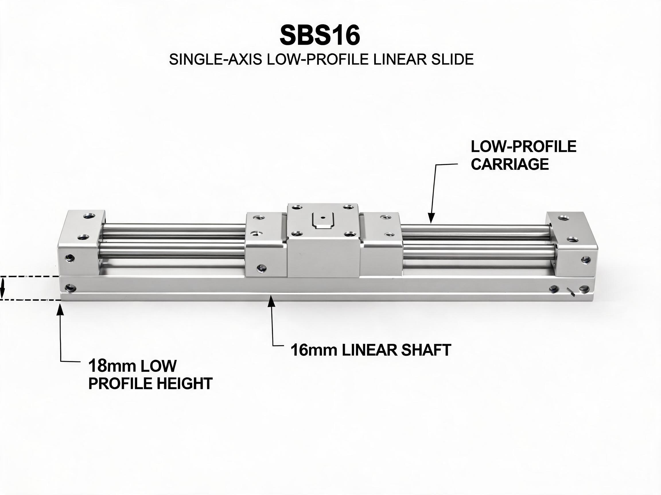
The SBS16 low-profile slide unit: 18 mm total system height, 16 mm hardened shaft on aluminum support rail. Integrated design saves vertical space in height-constrained beds.
Load and accuracy checklist
Height is only one dimension. Load capacity and accuracy requirements determine whether a component will perform reliably over time.
Load calculation
- Identify the moving mass: Include the carriage, toolhead, bed plate, and any workpiece. For the Y-axis, the bed and printed part mass can be significant.
- Determine dynamic load: The SBS16 provides 5.2 kN dynamic load capacity. The EGH15CA offers 5.5 kN dynamic and 9.2 kN static. Compare these ratings to your calculated loads with a safety factor appropriate to your duty cycle, and confirm the factor with the supplier.
- Consider moment loads: Off-center loads create moments that reduce effective capacity. Mount the carriage as close to the load center as possible.
Accuracy and repeatability
- Z-axis repeatability: The SFU1605 C7 rolled ball screw has a lead accuracy of ±0.05 mm per 300 mm. Lead accuracy alone is not the whole repeatability picture — nut preload, axial play, end supports and drive alignment all contribute. With the pre-loaded nut and proper end supports, this screw meets the sub-0.1 mm practical requirement of most desktop builds; confirm the complete assembly against your own positioning budget.
- Carriage precision: The EGH15CA uses a two-row Gothic-arch circuit and P5 ground raceway, which provides smooth motion and low friction. This contributes to print quality on the X-axis.
- Backlash: Ball screws can have some axial play; consider anti-backlash nuts if your Z-axis requires zero backlash. The C7 grade is a rolled screw, so backlash may be higher than ground screws; assess whether it meets your needs.
Speed and acceleration
- Lower moving mass allows higher acceleration. The EGH15CA carriage at 0.038 kg is lightweight, which is beneficial for fast X-axis moves.
- For Y-axis, if the bed mass is high, a low-profile slide unit with high load capacity may be more suitable than a miniature rail.
- Ball screws are generally not used for high-speed axes due to critical speed limitations; they are best for Z-axis where speed is low.
Component families in detail
Low-profile slide units for height-constrained beds
The SBS16 low-profile slide unit combines a 16 mm hardened shaft with an aluminum support rail, resulting in an 18 mm total system height. It is pre-assembled, which simplifies installation and reduces assembly time. With a dynamic load capacity of 5.2 kN, it can handle typical desktop bed loads; compare the rating against your calculated moving mass with an appropriate safety factor and confirm with the supplier. Standard lengths are 150–500 mm, and the mounting pitch is 25 mm. This unit is a good fit for Y-axis or any axis where vertical space is limited and a self-supporting shaft is advantageous.
Miniature profile rails for precision carriages
The EGH15CA miniature guideway features a two-row Gothic-arch circuit and P5 ground raceway, which provide high rigidity and smooth motion. The carriage weighs only 0.038 kg, making it suitable for lightweight X-axis carriages. Dynamic load is 5.5 kN and static load is 9.2 kN. Rail widths range from 9 mm to 15 mm across the series, with the EGH15CA running on a 15 mm wide rail. For applications requiring corrosion resistance, an MGN stainless miniature series is also available. This family is ideal for precise, high-speed carriages.
C7 ball screws for Z-axis drive
The SFU1605 C7 rolled ball screw has a 5 mm lead and a dynamic load capacity of 6.8 kN. Its lead accuracy is ±0.05 mm per 300 mm, which is sufficient for the sub-0.1 mm repeatability needed in desktop FDM Z-axes when the nut preload and end supports are correctly specified. Rolled screws are cost-effective compared to ground screws, though they may have slightly lower accuracy. For most desktop printers, the C7 grade provides a good balance. This screw can also be used on X or Y axes if the speed requirements are moderate.
FAQ
Can I use a ball screw for the X-axis?
Yes, but consider the speed. Ball screws are efficient and precise, but they have a critical speed limit. For high-speed X-axes, a belt drive or linear rail with a lightweight carriage may be more suitable. The SFU1605 can be used on X or Y if your speeds are moderate and you need precise motion.
What is the difference between C7 and C5 ball screws?
C7 is a rolled screw with a lead accuracy of ±0.05 mm per 300 mm. C5 is a ground screw; on our SFE2005 ground assembly, lead accuracy is ±0.008 mm per 300 mm with axial play below 0.005 mm from the pre-loaded double nut. For 3D printing, C7 is usually sufficient unless your design demands ground-screw accuracy or near-zero axial play.
How do I choose between a low-profile slide unit and a miniature rail?
Choose a low-profile slide unit when vertical space is limited and you need a self-supporting shaft over a long span. Choose a miniature rail when you need a compact, rigid carriage for precise motion, especially on the X-axis where moving mass should be minimized.
Are stainless steel rails available for corrosive environments?
The MGN stainless miniature series is available for applications where corrosion resistance is needed. The EGH series standard material is chrome steel (GCr15); confirm material options with the supplier if stainless is required for a specific build.
For specific load calculations or to discuss your printer's requirements, contact our engineering team. We can help you select the right linear motion components for your desktop FDM design.