
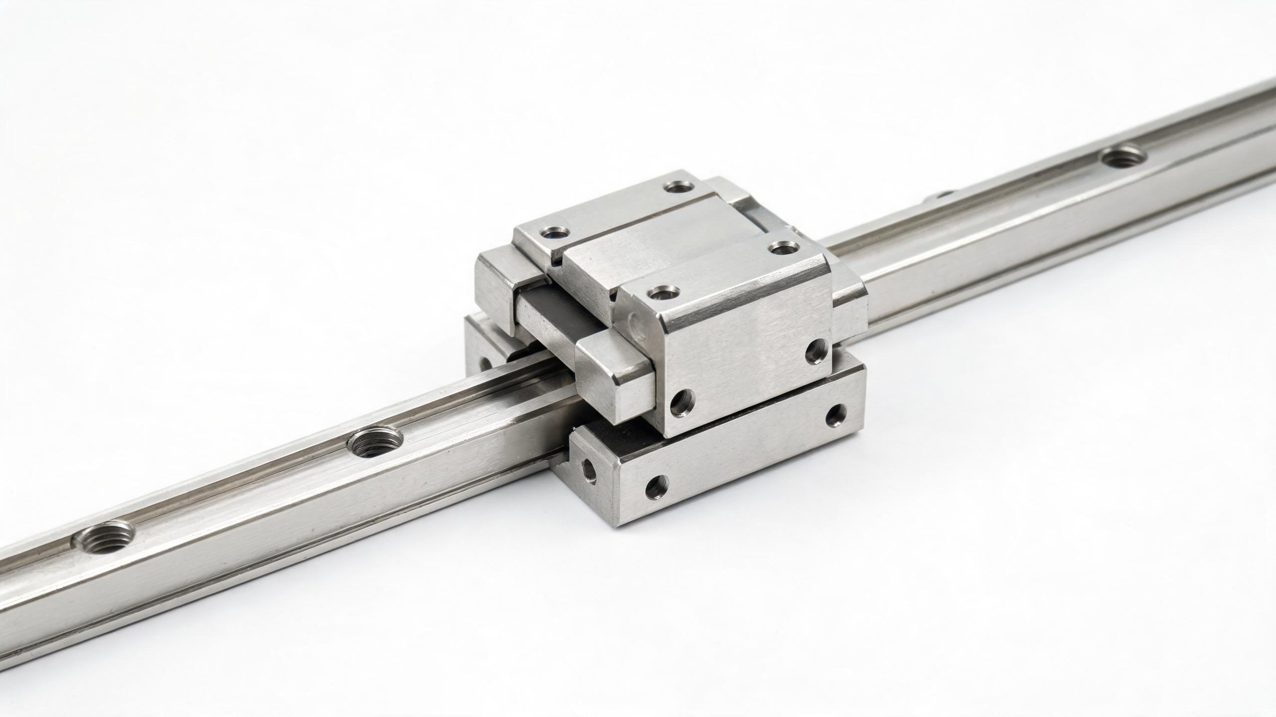
A practical engineering guide for procurement and design teams evaluating large-format linear guideways. Covers HGR45 rail selection criteria, static/dynamic load rating calculations, rigidity verification, preload classes, and CNC machine tool integration considerations — with a comparison table and supplier evaluation checklist.
BUYER ENGINEERING GUIDE
When you are sourcing linear guideways for a gantry mill, a heavy-duty machining center, or a large-format CNC router, the HGR45 rail size is often the first serious step up from medium-duty profiles. It is not a component you pick by feel. The rail size, block count, preload class, and mounting pattern must be verified against your actual cutting forces, workpiece weight, and duty cycle.
This guide covers the engineering decisions behind HGR45 selection — load rating calculation, rigidity verification, and integration into CNC machine tool assemblies — so you can spec the correct rail linear system the first time and avoid costly redesigns.
- HGR45 refers to a 45 mm wide rail with a nominal block height of 70 mm — verify the exact rail width and mounting hole pitch against the manufacturer's dimensional drawing before ordering.
- Always calculate both static and dynamic load ratings; the smaller of the two often governs in heavy milling applications.
- Rigidity is a function of preload class, block count, and mounting surface stiffness — not just rail size.
- For CNC integration, confirm the rail straightness grade and the recommended bolt torque for your machine base material.
What the HGR45 Size Actually Means
The HGR45 designation follows the common HGR series naming convention used across many Asian linear guide manufacturers. The "45" refers to the nominal rail width in millimeters. Typical dimensions for this size class are:
| Parameter | Typical Value (HGR45) |
|---|---|
| Rail width (W) | 45 mm |
| Block height (H) | 70 mm |
| Block width (W1) | 86 mm |
| Mounting hole pitch (F) | 60 mm (verify per drawing) |
| Dynamic load rating (C) | Approx. 77–80 kN (per block, verify) |
| Static load rating (C0) | Approx. 110–120 kN (per block, verify) |
These figures are representative of the size class. The exact values depend on the manufacturer's internal geometry, ball circuit design, and material grade. Always request the manufacturer's specification sheet and compare the load ratings and dimensional tolerances against your application requirements.
Sizing the Right Rail Linear System: Start with Loads, Not Habits
The most common mistake in sizing a rail linear bearing block is selecting the rail size based on what the previous machine used. The correct approach is to calculate the actual loads acting on each block under the worst-case cutting condition.
Step 1: Define the Applied Loads
For a CNC machine tool, the loads on the linear guideways come from three sources:
- Workpiece and table weight — static load distributed across all blocks.
- Cutting forces — dynamic loads from milling, drilling, or turning operations. These are rarely centered; they create moments about the guide axes.
- Acceleration/deceleration forces — inertial loads during rapid traverse, especially relevant for large gantries.
Step 2: Calculate the Equivalent Load per Block
For a four-block carriage with the load centered, each block carries roughly one-quarter of the total vertical load. But when the cutting force is offset — which it almost always is — the corner blocks see significantly higher loads. The standard method is to calculate the load on each block by resolving forces and moments about the carriage center, then use the maximum block load for the life calculation.
Step 3: Apply the Dynamic Load Rating Formula
The basic dynamic load rating (C) is the load at which the bearing achieves a rated life of 100 km. The life equation is:
L = (C / P)³ × 100 km
where L is the rated life in kilometers, C is the dynamic load rating, and P is the equivalent dynamic load on the most heavily loaded block. The exponent is 3 for ball-type linear guides, which is what the HGR series uses.
For a target life of 20,000 hours at a typical feed rate of 10 m/min, the required life in kilometers is 12,000 km. Working backward, you can solve for the maximum allowable equivalent load P and compare it against your calculated worst-case block load.
Rigidity Calculation: The Part Most Buyers Skip
Load rating tells you whether the guide will survive. Rigidity tells you whether the machine will hold tolerance. For a large-format CNC machine, the rigidity of the linear guideways directly affects machining accuracy, surface finish, and chatter behavior.
Preload Class Selection
Preload is the internal clearance (or interference) set between the balls, raceways, and block. Higher preload increases rigidity but also increases friction and heat generation. The HGR series typically offers these preload classes:
| Preload Class | Internal Clearance | Typical Application |
|---|---|---|
| ZF (light preload) | Zero to slight clearance | General positioning, low friction required |
| Z0 (medium preload) | Zero clearance | General machining, single-axis applications |
| Z1 (heavy preload) | Interference fit | CNC machining centers, heavy cutting, high rigidity |
For a CNC machine tool performing heavy milling, Z1 preload is the standard choice. The increased friction is acceptable because the rigidity gain directly translates to better surface finish and dimensional accuracy.
Calculating Deflection
The total deflection of a linear guide system under load has three components:
- Ball contact deflection — the elastic deformation at the ball-raceway contact points. This is the dominant component and is provided by the manufacturer as a rigidity value (N/µm) for each preload class.
- Rail bending — the deflection of the rail itself between mounting bolts. For a 45 mm rail with a 60 mm bolt pitch, this is usually small but becomes significant on long unsupported spans.
- Mounting surface deflection — the compliance of the machine base or bed. This is often the largest contributor to total system deflection and is entirely under your control.
For a quick check: if the manufacturer specifies a rigidity of 800 N/µm per block for the Z1 preload class, a four-block carriage with a 40 kN cutting load would see approximately 12.5 µm of deflection from ball contact alone. Add the mounting surface deflection, and the total can easily reach 25–40 µm — enough to affect a tolerance of ±0.02 mm.
The rail linear system is only as rigid as the surface it is bolted to. A scraped or ground mounting surface with proper bolt torque will outperform a larger rail bolted to a poorly prepared base.
CNC Machine Tool Integration: Mounting, Alignment, and Protection
Integration is where engineering theory meets shop-floor reality. Here are the critical points to verify with your supplier before placing an order.
Mounting Surface Preparation
The mounting surface must be machined flat and parallel. The recommended flatness is typically 0.01 mm per 1000 mm of length for heavy-duty applications. The surface should be ground or precision-milled; a scraped surface is acceptable if the bearing area is adequate.
Bolt Selection and Torque
HGR45 rails are typically mounted with M8 or M10 socket head cap screws. The recommended tightening torque depends on the bolt grade and the base material. For a steel base with 12.9-grade bolts, the typical torque range is 25–35 N·m for M8 and 50–70 N·m for M10. Verify the manufacturer's recommendation — under-torquing causes the rail to shift under load, and over-torquing distorts the rail and causes premature ball wear.
Rail Straightness and Alignment
For CNC applications, specify the higher straightness grade (often designated as "H" or "P" grade). The straightness tolerance is typically 0.003 mm per 1000 mm for the precision grade. During installation, use a precision straightedge and dial indicator to check the rail straightness in both the horizontal and vertical planes. The two rails on a single axis must be parallel within 0.01 mm over the full travel.
Lubrication and Protection
Large-format machines often operate in dirty environments — cast iron dust, coolant mist, and abrasive particles. The HGR45 block should be ordered with the appropriate lubrication fitting (grease nipple or oil port) and, for exposed applications, a wiper seal or telescopic cover. Confirm the lubrication interval with the manufacturer; for heavy-duty machining, regreasing every 50–100 operating hours is common.
Comparison: HGR45 vs. Other Rail Linear Sizes
To help you position the HGR45 against adjacent size classes, here is a practical comparison based on typical specifications for the HGR series:
| Size Class | Rail Width (mm) | Block Height (mm) | Dynamic Load Rating (kN) | Typical Application |
|---|---|---|---|---|
| HGR35 | 35 | 55 | ~48 | Medium CNC, light gantries |
| HGR45 | 45 | 70 | ~77–80 | Heavy CNC, large gantries, machining centers |
| HGR55 | 55 | 80 | ~120 | Extra-heavy duty, large boring mills |
If your application sits between the HGR45 and HGR55, the deciding factor is usually rigidity rather than load capacity. The HGR55 offers roughly 50% more dynamic load rating and significantly higher stiffness. If your machine must hold tight tolerances on large workpieces, the price premium for the larger size is often justified.
Supplier Evaluation Checklist for HGR45 Linear Guideways
When evaluating suppliers for rail linear systems, use this checklist to separate engineering partners from parts resellers:
- Dimensional drawing: Does the supplier provide a detailed dimensional drawing with tolerances? A serious manufacturer will have this available for download.
- Load rating data: Are the dynamic and static load ratings published per block? Are the test conditions stated?
- Rigidity curves: Does the supplier provide rigidity values (N/µm) for each preload class? This is essential for the deflection calculation.
- Straightness grade: Can the supplier guarantee the straightness grade in writing? Ask for the inspection certificate.
- Material and hardness: What steel grade is used, and what is the case hardness (typically HRC 58–62 for the raceway)?
- Customization: Can the supplier cut rails to length, drill custom mounting holes, or supply matched sets with a single block? For large CNC builds, matched sets reduce installation time.
- Lead time and MOQ: Confirm the lead time for the specific length and preload class you need. Non-standard preload classes often have longer lead times.
FAQ: HGR45 Selection and Integration
Q: Can I use HGR45 rails with blocks from a different manufacturer?
Technically possible only if the cross-sectional dimensions and mounting hole patterns match exactly. In practice, mixing brands is risky because the internal raceway geometry and ball circuit design differ, which affects load distribution and preload consistency. For a CNC machine tool, use matched rails and blocks from a single manufacturer.
Q: How many blocks should I use per rail?
For a heavy-duty CNC machine, two blocks per rail (four total) is the standard configuration. If the carriage is very long or the loads are high, three blocks per rail can be used, but the middle block must be allowed to float slightly to avoid over-constraint. Discuss this with your supplier before ordering.
Q: What is the maximum rail length I can order?
This depends on the manufacturer's production capability and transport constraints. Many manufacturers produce rails up to 4 meters in standard lengths and can butt-joint longer rails. For rails over 4 meters, confirm the straightness specification and the jointing method with your supplier.
Q: How do I know if I need the Z1 (heavy) preload?
If your machine performs intermittent heavy cutting (milling, boring) and you require high rigidity, choose Z1. If the application is primarily positioning or light cutting, Z0 is sufficient and will run cooler. When in doubt, request the rigidity curves from your supplier and calculate the deflection at your worst-case load.
Next Steps for Your Project
Sourcing the correct HGR45 linear guideways is a matter of verifying load ratings, calculating rigidity, and confirming integration details with your supplier. Share your machine's cutting force data, workpiece weight, and duty cycle with your supplier — a competent manufacturer will help you verify the sizing rather than simply confirming your order.
If you are currently evaluating linear guideways for a large-format CNC machine, we welcome your inquiry. Send us your application parameters — table size, maximum workpiece weight, spindle power, and expected cutting forces — and we will help you verify the HGR45 sizing or recommend the appropriate size class. Our team can provide dimensional drawings, load rating data, and rigidity curves for your review before you commit to a purchase order.