
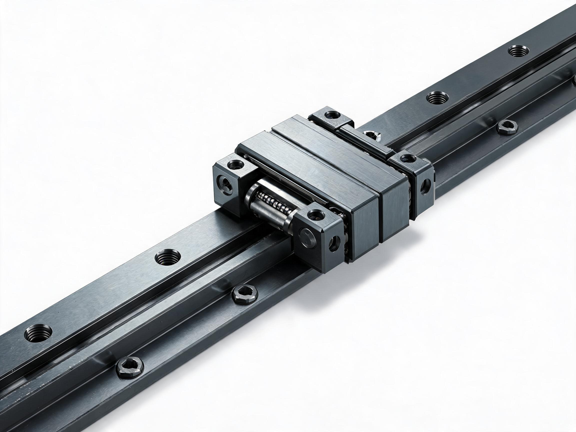
A step-by-step installation sequence for profile linear guide rails, from goods-inward inspection to the first travel of the carriage, with the acceptance check that must be signed off before each next step begins.
Many linear guide rail problems surface at the first travel of the carriage, when the whole chain — bed, rail, carriage and lubrication — finally moves under power. They usually trace back to a step that was accepted without checking the result. This article sets out the order we recommend for fitting profile rails to a machine bed, and the specific acceptance check that must pass before the next step starts. The order matters because a check that comes too late cannot separate one cause from another: flatness, pitch, parallelism, and carriage preload all produce similar symptoms once the machine is assembled.
The rail data below refers to the HGR series we build: 55# high-carbon steel body, induction-hardened raceway at 58–62 HRC, four-row ball circuit, sizes HGR15 through HGR45, available in ground precision H grade (P5 equivalent) and rolled N grade (P7). The HGR20 carries a listed dynamic load of 16.7 kN and static load of 26.7 kN. Standard rail length is up to 4000 mm; longer runs are supplied as precision-spliced sections. The cross-section and bolt-hole pitch are interchangeable with the standard Taiwanese HGR profile — the interchange covers the envelope dimensions only, and precision grade, preload and load ratings must still be confirmed against the drawing and the datasheet.
Detailed topics are published separately: mounting hole pitch and bolt selection, base flatness preparation, and two-rail parallelism measurement. This article references them where the sequence reaches them and does not repeat their methods.
- Work in a fixed order, and treat each step's acceptance check as a gate, not a formality.
- Complete the bed preparation and the base reference before any rail is set down.
- Confirm rail grade, size, and splice positions against the drawing before the first bolt is tightened.
- The first travel is a test of the whole chain: bed, rail, carriage, lubrication.
Step 1 — Goods-inward check before the rail reaches the bed
The first acceptance check happens with the rail still in its packaging. Compare the label, the packing list, and the drawing: series, size, length, precision grade, and hole pattern. A ground H grade rail and a rolled N grade rail look similar in cross-section, and mixing them on one axis will show up later as inconsistent running, with no obvious cause. Record the grade of each rail before it leaves the receiving area.
Unpack long rails on a flat, clean surface with support along their length. A rail overhanging a bench can take a bend that is not visible after it is bolted down. Check the rail body for dents, rust, and handling marks on the raceway, and confirm the carriage moves freely by hand over its full stroke. If a rail is supplied as precision-spliced sections for a run beyond 4000 mm, check that the section ends, joint markings, and the splice positions match the drawing. Do not straighten a bent rail by force; stop and raise it with the supplier.
Step 2 — Bed preparation and the base reference
No rail should be placed on the bed until the mounting surface has been prepared and measured. The base flatness article covers measurement in detail; the check here is simply that the measured result on the bed is recorded and accepted before rails are laid out. Clean the surface, remove burrs around the tapped holes, and confirm the holes are clear and to the correct depth.
Decide the reference edge at this point. On most machine beds, one rail is aligned to a machined shoulder or reference edge, and the second rail is positioned from that first rail. Mark both positions and the direction of travel on the bed. If shims or a spacer are required, confirm the thickness and tightening sequence with the datasheet or your supplier before fitting, and check that the reference edge is intact along the full rail length.
Step 3 — Place and align the reference rail
Set the reference rail down without forcing it, and confirm the bolt holes line up with the tapped holes without side pressure. Bolt selection and pitch were settled in the separate article; here the check is that the correct bolts are present, the rail is not held off the surface by debris, and the rail sits against its reference edge along the length. Hand-tighten the bolts from the middle outward so the rail is drawn down evenly, then tighten to the value in the datasheet or supplied by your supplier. Do not use torque values from another rail brand.
After tightening, check that the rail does not lift from the bed and that the reference edge contact is continuous. A straightedge laid along the rail, or a dial indicator on the rail top, confirms the result before the second rail is positioned. If the rail is already out of line at this stage, correcting it later means loosening the whole row.
Step 4 — Position the second rail and confirm parallelism
The second rail is positioned from the first, not from the bed edge. The parallelism deep-dive covers the measurement method; the gate here is that both rails are measured, the reading is recorded, and the result is within the tolerance set for the machine. Check along the whole length and at both ends, since a rail that is parallel at the middle can still diverge at the ends.
With both rails bolted, move the carriage or a gauge across the pair to confirm the gap does not vary beyond the accepted range. This is the last point at which parallelism can be corrected with the rails in place. For the larger frames that use the HGR series heavy-duty linear guideway rail, the same order applies; the acceptance numbers come from the machine drawing, not from the rail catalogue alone.
Step 5 — Fit the carriage and connect lubrication
Slide the carriage onto the rail from the end, using the plastic insertion guide supplied with the block. Do not press the carriage over the rail with the balls exposed, since this can displace a ball and damage the circuit. The HGR rail has a continuous oil groove along the body, and the carriage has lubrication ports; connect the supply and confirm grease or oil is present before any travel is commanded. Whether the machine uses grease or oil, and at what interval, should follow the datasheet or your supplier's recommendation.
Confirm the carriage moves by hand over its full stroke with no tight spot and no rattle. This hand check is the gate before the axis is driven under power.
Step 6 — First travel and final verification
Run the axis first at low speed and short stroke, then extend the stroke and speed in stages. Watch for changes in sound, vibration, and motor load across the full length. A tight spot at one position usually points to a high point on the bed or a rail that was tightened out of sequence, while a drift in one direction points to parallelism. Because the earlier checks were recorded, you can compare the symptom with the readings already on file rather than reinstalling blindly.
Confirm the carriage runs the full stroke without fouling, the lubrication supply is working, and the readings from steps 2 to 4 are repeated with the machine assembled. Record the final result, including rail grade and size, for the machine file. If a machine uses the larger HGR45 heavy-duty large linear guideway rail, keep the same sequence; the difference is in handling and support of the heavier rail, not the order of checks.
Hand-off checks at a glance
| Step | What is completed | Gate before the next step |
|---|---|---|
| 1. Inward check | Grade, size, length, and hole pattern confirmed; carriage moves freely | Each rail tagged with its grade; no damaged rail released to the bed |
| 2. Bed preparation | Surface cleaned, holes checked, reference edge marked | Base flatness measured and accepted; shim/spacer confirmed with supplier |
| 3. Reference rail | Rail set down, bolted from the middle outward | Rail seated on bed and against reference edge along full length |
| 4. Second rail | Second rail positioned from the first | Parallelism measured and recorded within drawing tolerance |
| 5. Carriage and lube | Carriage fitted with insertion guide; supply connected | Full-stroke hand travel with no tight spot |
| 6. First travel | Axis run at low speed and extended in stages | Sound, load, and readings checked and filed |
Frequently asked questions
Should the carriage be fitted before or after the rails are bolted down?
Fit the carriage after the rails are bolted. Sliding it on earlier makes the rail harder to align and risks ball damage during tightening.
Can a rail longer than 4000 mm be supplied as one piece?
Standard rail length is up to 4000 mm. Longer runs are supplied as precision-spliced sections, and the splice positions need to be checked against the drawing at goods-inward.
What if the first travel shows a tight spot at one position?
Compare it with the flatness and parallelism readings already recorded. The position of the tight spot usually indicates whether the cause is on the bed or in the rail alignment.
Which precision grade should be ordered for a machine bed?
The rail is available in ground H grade (P5 equivalent) and rolled N grade (P7). The machine drawing or application requirement decides the grade; confirm it before ordering, since the two grades should not be mixed on the same axis.
If you are specifying rails for a new machine bed, the HGR series product page lists sizes, grades, and rail lengths. Confirm torque values, shim thickness, and lubrication intervals against the datasheet or with your supplier, because those depend on the machine and the bolt used.