
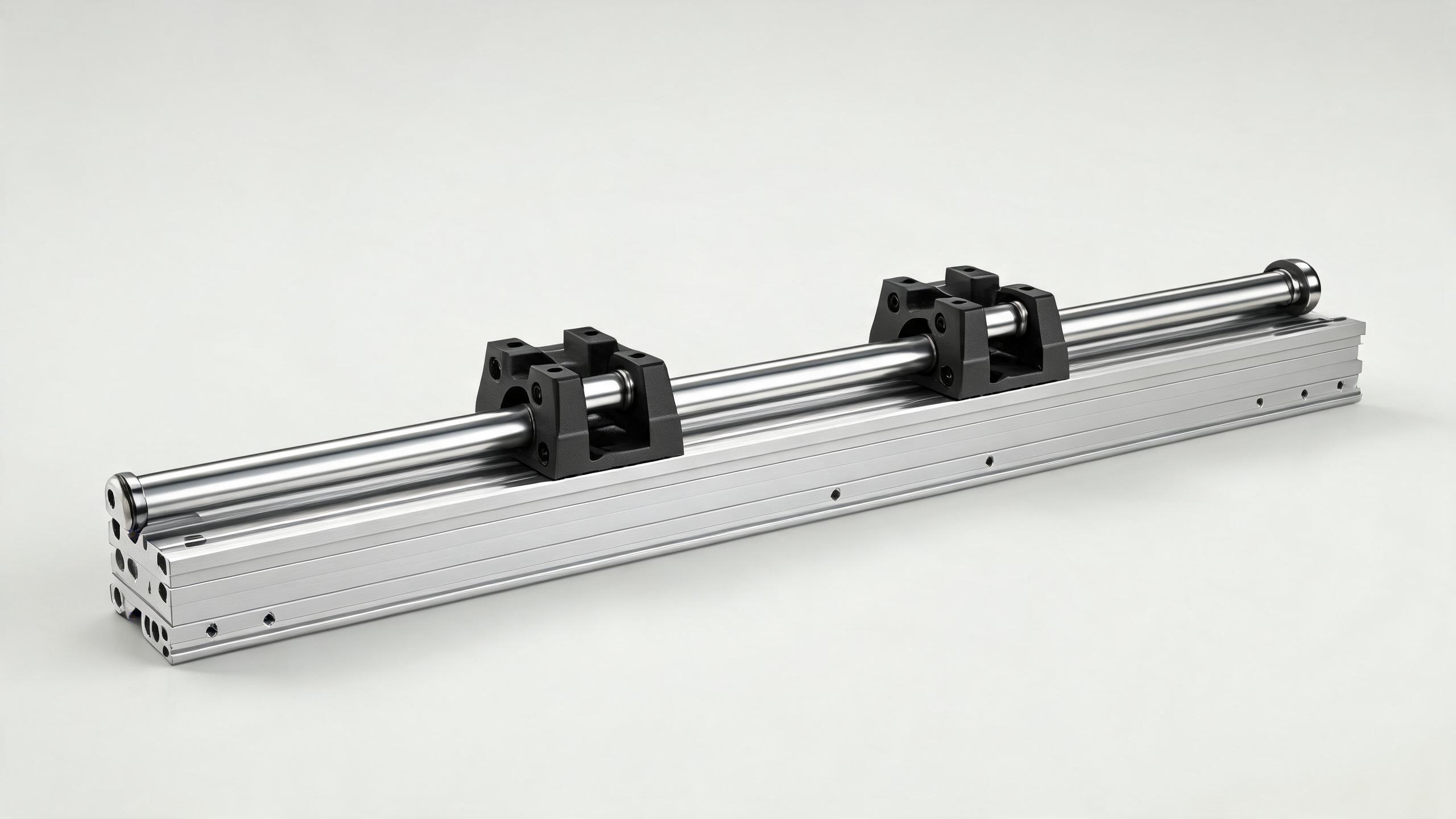
A practical guide to linear guide systems for B2B buyers and automation engineers. Covers rail profile types (ball vs. roller, standard vs. wide), carriage configurations, preload and accuracy classes, mounting and integration considerations, and a supplier evaluation checklist. Written for procurement teams who need to specify the right linear rail system without over- or under-engineering.
BUYER GUIDE · LINEAR MOTION
Linear Guide Systems: Rail Types, Carriage Configurations, and Integration for Automation Equipment
When a machine builder specifies a linear guide system, they are not buying a component. They are buying predictable motion — repeatable positioning, controlled friction, and a known service life under a defined load. The problem is that the market offers dozens of rail profiles, carriage styles, preload classes, and accuracy grades. Choosing wrong means either paying for precision you do not need, or replacing the carriage six months after installation.
This guide is written for procurement engineers and automation integrators who need to specify a linear rail system with confidence. We cover the four decisions that matter most: rail profile, carriage configuration, preload and accuracy class, and integration method. Each section gives you the criteria to make the call, not a sales pitch.
- Ball-type rails suit high-speed, moderate-load applications; roller-type rails suit heavy-load, high-rigidity applications. Match the rolling element to the actual load, not the datasheet maximum.
- Carriage width, mounting hole pattern, and seal type are as important as the rail profile. A wide carriage doubles moment capacity in many cases — often cheaper than upsizing the rail.
- Preload and accuracy class are independent specifications. Do not assume a C3 ground rail comes with light preload; confirm both on the drawing.
- Integration failures are usually mounting-surface errors, not component failures. Specify flatness and parallelism tolerances on the mating surface, and verify them at incoming inspection.
- Ask your supplier for load-life calculation reports. A supplier who provides them has done the engineering work; one who only sends a quote has not.
Why the Linear Guide Rail System Is the Backbone of Automation
A linear guide rail system does one job: it constrains a moving carriage to a straight line while carrying a load. That sounds simple, but the performance of every downstream process depends on it. In a pick-and-place machine, the guide determines whether the gripper lands within ±0.01 mm or drifts. In a CNC router, it determines surface finish quality. In a packaging line, it determines whether the sealing head aligns with the film seam.
The cost of a guide rail is typically 3–8% of a machine's total build cost. Yet it is the component most likely to cause downtime if mis-specified. That is why buyers should spend more time on the selection logic than on the unit price.
Rail Types: Ball vs. Roller, Standard vs. Wide
The rail profile is the first decision. Two factors dominate: the rolling element type and the rail width.
Ball-Type Linear Guide Systems
Ball-type systems use recirculating steel balls between the rail and the carriage. They are the most common configuration in automation equipment.
Strengths:
- Low friction coefficient (typically 0.001–0.004), which means smooth motion even at low speeds.
- High speed capability — ball-type carriages can run at linear speeds of several meters per second with proper lubrication.
- Good balance of load capacity and cost. For most pick-and-place, assembly, and inspection applications, a ball-type rail is sufficient.
- Wide availability of standard sizes (rail widths from 15 mm to 65 mm are common).
Limitations:
- Lower rigidity compared to roller types under moment loads. If your application involves high overturning moments, a ball-type rail may flex more than you want.
- Shorter fatigue life under very heavy loads, because the contact area between ball and raceway is small.
Roller-Type Linear Guide Systems
Roller-type systems use cylindrical rollers instead of balls. The line contact between roller and raceway distributes load over a larger area.
Strengths:
- 1.5 to 2 times the load capacity of a comparable ball-type rail of the same size.
- Higher rigidity, especially under moment loads. This matters for heavy machining, stamping, and large-format gantry applications.
- Better damping characteristics, which helps with vibration-sensitive processes.
Limitations:
- Higher friction and slightly higher running noise.
- More sensitive to mounting surface accuracy — the rail and carriage must be aligned within tighter tolerances.
- Higher cost per unit.
Standard vs. Wide Rail Profiles
Within both ball and roller types, you can choose a standard-width rail or a wide rail (sometimes called "wide carriage" or "LW" series). The wide profile uses the same rail height but a wider carriage footprint.
When to choose wide:
- The application has significant moment loads (pitching, yawing, or rolling).
- The machine has space constraints on height but not on width.
- You want to avoid upsizing to the next rail width, which would increase cost and require a larger mounting surface.
A wide carriage of the same rail size typically doubles the dynamic moment capacity in the pitch and roll directions. If your load is offset from the carriage center, this is the most cost-effective fix.
| Selection Criterion | Ball Type | Roller Type |
|---|---|---|
| Typical load range (per carriage) | 0.5 – 20 kN | 2 – 60 kN |
| Friction coefficient | 0.001 – 0.004 | 0.002 – 0.006 |
| Max speed | High (several m/s) | Moderate (up to ~2 m/s) |
| Rigidity under moment load | Moderate | High |
| Typical applications | Pick-and-place, assembly, inspection, packaging | CNC machining, heavy gantries, stamping, large-format printers |
| Relative cost | Baseline | 1.5 – 2.5× baseline |
Carriage Configurations: What You Are Actually Specifying
The carriage is the part that moves. It contains the recirculating balls or rollers, the return channels, and the seals. When you specify a carriage, you are specifying four things:
1. Carriage Width and Length
Carriage length affects load distribution. A longer carriage spreads the load over more rolling elements, which increases dynamic load capacity. However, it also increases the overall envelope and weight.
A common mistake is to select a carriage based only on rail size. Two carriages of the same rail width can have very different load ratings depending on length. Check the dynamic load rating (C) on the datasheet, not just the rail profile.
2. Mounting Hole Pattern
Carriages come with either tapped holes or through-holes for mounting. The pattern is standardized within each rail size series, but the number of holes varies with carriage length.
- Tapped holes: Common for smaller carriages (size 15–25). You bolt the carriage directly to the moving plate.
- Through-holes: Common for larger carriages. You use bolts with nuts on the underside, which allows for a thinner mounting plate.
For integration, confirm the hole pattern matches your plate design before ordering. Custom hole patterns are available from most manufacturers but add lead time and cost.
3. Seal Type
Seals keep contamination out and lubrication in. This is more important than most buyers realize.
- Standard seals (contact type): A rubber lip that contacts the rail. Suitable for clean or lightly dusty environments.
- Low-friction seals: A lighter lip for high-speed applications where seal drag matters.
- Scraper seals (double seals): Two-stage sealing for dusty or debris-heavy environments like woodworking or welding cells.
- Stainless steel seals: For applications where the seal must withstand aggressive washdown or chemical exposure.
If your machine runs in a dusty environment, a standard seal will fail prematurely. The cost difference between standard and scraper seals is small; the downtime cost of a failed carriage is not.
4. Lubrication Fitting
Carriages typically have a grease nipple on the end face or the side. For automated lubrication systems, confirm the fitting type (M6 or M8 thread is common) and the grease port location. If the carriage will be mounted in a position where the nipple is inaccessible, specify a side-mounted fitting or a remote lubrication line.
Preload and Accuracy Class: Two Separate Decisions
Buyers often confuse preload with accuracy class. They are independent specifications.
Preload
Preload is the internal force applied between the rolling elements and the raceway to eliminate clearance. It affects rigidity, friction, and life.
- Zero clearance (Z0 / no preload): The rolling elements just touch the raceway. Lowest friction, but some play exists. Suitable for applications where load direction is constant and precision is moderate.
- Light preload (Z1 / P1): Small internal force. Good balance of rigidity and smoothness. Recommended for most general automation.
- Medium preload (Z2 / P2): Higher rigidity, higher friction. Suitable for machining, grinding, and applications with vibration.
- Heavy preload (Z3 / P3): Maximum rigidity, significant friction. Rarely used; only for very high stiffness requirements where speed is low.
A practical rule: for general automation, specify light preload. For machining or grinding, specify medium. Do not specify heavy preload unless you have a specific rigidity requirement — it increases heat generation and reduces service life.
Accuracy Class
Accuracy class refers to the geometric tolerances of the rail and carriage — straightness, height tolerance, and running parallelism. Common classes in the industry are:
- Normal (C / N): For general-purpose machines. Height tolerance around ±0.1 mm.
- High (H): For better consistency. Height tolerance around ±0.04 mm.
- Precision (P / C3): For high-precision equipment. Height tolerance around ±0.01 mm.
- Super precision (SP / C5) and Ultra (UP / C7): For metrology, semiconductor, and high-end CNC. Tolerances in the micron range.
The accuracy class affects cost significantly. A C3 ground rail can cost 2–3 times more than a normal-ground rail of the same size. Only specify high accuracy where the application requires it.
| Application | Recommended Preload | Recommended Accuracy Class |
|---|---|---|
| Pick-and-place, general assembly | Light (Z1) | Normal (C) or High (H) |
| Packaging, labeling, inspection | Light (Z1) | High (H) |
| CNC machining, grinding | Medium (Z2) | Precision (P) |
| Semiconductor, metrology | Medium (Z2) | Super precision (SP) |
Integration for Automation Equipment: Mounting and Alignment
The best rail system in the world will fail if the mounting surface is wrong. Integration issues are the most common cause of premature guide failure.
Mounting Surface Requirements
The mating surface — the machine base or the moving plate — must meet specific tolerances for flatness and parallelism. Typical requirements:
- Flatness: 0.01 mm per 100 mm of length for precision applications; 0.02–0.03 mm per 100 mm for general automation.
- Parallelism between the two rails: 0.02 mm per meter is a common starting point.
If the surface is out of tolerance, the rail will distort when bolted down. This causes increased friction, uneven load distribution, and premature wear. The solution is not a better rail — it is a better mounting surface.
Rail Mounting Methods
- Bolted with dowel pins: The standard method. The rail is bolted down, and dowel pins provide precise lateral location. Suitable for most applications.
- Adhesive bonding: Used for very thin rails or where bolting is not possible. Requires careful surface preparation and curing time.
- Clamping: Used in adjustable setups where the rail position may need to change. Less rigid than bolting.
Alignment Procedure
For a dual-rail system, the alignment procedure is critical:
- Mount the primary rail, bolt it down, and verify straightness with a dial indicator.
- Mount the secondary rail loosely.
- Use a straightedge or a laser alignment tool to set the parallelism between the two rails.
- Torque the secondary rail bolts progressively from the center outward.
A common mistake is to tighten the secondary rail bolts from one end to the other, which can induce bending. Progressive torquing from the center avoids this.
Thermal Expansion
Steel rails expand at approximately 11–12 µm per meter per 10°C. If your machine operates in a temperature-controlled environment, this is negligible. If not, you must account for it:
- Leave a small gap at the rail joint for long rails (over 2–3 meters).
- Use a fixed reference point at one end and allow free expansion at the other.
- Consider the thermal expansion of the machine base, not just the rail.
Common Specification Mistakes to Avoid
-
Oversizing the rail. A 35 mm rail is not "better" than a 25 mm rail if your load only requires 20 mm. You pay more, and the larger rail requires a larger mounting surface, more bolts, and more space.
-
Ignoring moment loads. Many applications have loads offset from the carriage center. Calculate the moment (load × distance) and check it against the moment capacity of the carriage, not just the vertical load rating.
-
Forgetting the seals. If your environment has dust, chips, or moisture, standard seals will fail. Specify scraper seals or stainless steel covers.
-
Not verifying the mating surface. A precision rail on a poorly machined surface is a waste of money. Verify flatness and parallelism before installation.
-
Choosing accuracy class by habit. If your previous machine used C3, you may not need it for the next one. Match the accuracy class to the process requirement.
Supplier Evaluation Checklist
When evaluating a linear guide system supplier, ask for the following:
- Load-life calculation report. A document showing the expected service life (in kilometers of travel) for your specific load and speed. A supplier who provides this has done the engineering work.
- Technical datasheet with dimensions. Confirm the rail width, height, mounting hole pattern, and carriage dimensions match your design.
- Accuracy and preload confirmation. Get the accuracy class and preload written on the quotation, not just "precision grade."
- Material and hardness specification. Most rails are made of bearing steel (GCr15 or equivalent) hardened to 58–62 HRC. Confirm this on the datasheet.
- Lead time and MOQ. Linear guide systems are often custom-ordered in batches. Confirm the lead time for your specific rail length and accuracy class.
- Customization capability. If you need special rail lengths, custom hole patterns, or special coatings (e.g., black oxide for corrosion resistance), confirm the supplier can do it and at what lead time.
FAQ: Quick Answers for Buyers
Q: What is the difference between a linear guide and a linear bearing? A: A linear bearing (e.g., a ball bushing) runs on a round shaft and has line contact. A linear guide runs on a profiled rail and has point or line contact with a machined raceway. Linear guides offer higher rigidity, higher accuracy, and higher load capacity, at a higher cost.
Q: Can I mix rails and carriages from different manufacturers? A: Not recommended. Rail and carriage are matched for preload and accuracy. Mixing brands can cause uneven load distribution and premature wear. If you must, confirm the interchangeability standard (many manufacturers follow ISO or DIN standards), but the safest path is to source both from the same supplier.
Q: How often should I lubricate the carriage? A: It depends on speed, load, and environment. As a starting point, grease every 100 km of travel or every 3–6 months, whichever comes first. High-speed or dusty environments require more frequent lubrication.
Q: What is the typical service life of a linear guide system? A: With correct selection and lubrication, a ball-type guide can run 10,000–20,000 km of travel before fatigue failure. Roller-type guides last longer under heavy loads. The load-life calculation determines the expected life for your specific application.
Q: Can you supply custom rail lengths? A: Yes, most manufacturers cut rails to length. Confirm the maximum length per piece (typically 3–4 meters, depending on the series) and the lead time for custom lengths.
Final Recommendation
Specify the smallest rail that meets your load and rigidity requirements. Choose ball-type for general automation and roller-type for heavy loads or high rigidity. Use wide carriages to handle moment loads without upsizing the rail. Set preload to light for general use, medium for machining. Match accuracy class to the process requirement, not to habit.
Then verify the mounting surface, follow the alignment procedure, and keep the system lubricated. A correctly specified and properly installed linear guide rail system will outlast the machine it is mounted on. A poorly specified one will fail within months — and the cost of that failure is always higher than the cost of getting the specification right the first time.
For detailed load-life calculations, mounting surface specifications, or custom rail configurations, contact our engineering team with your application parameters. We will provide a written recommendation with the calculations to back it up.