
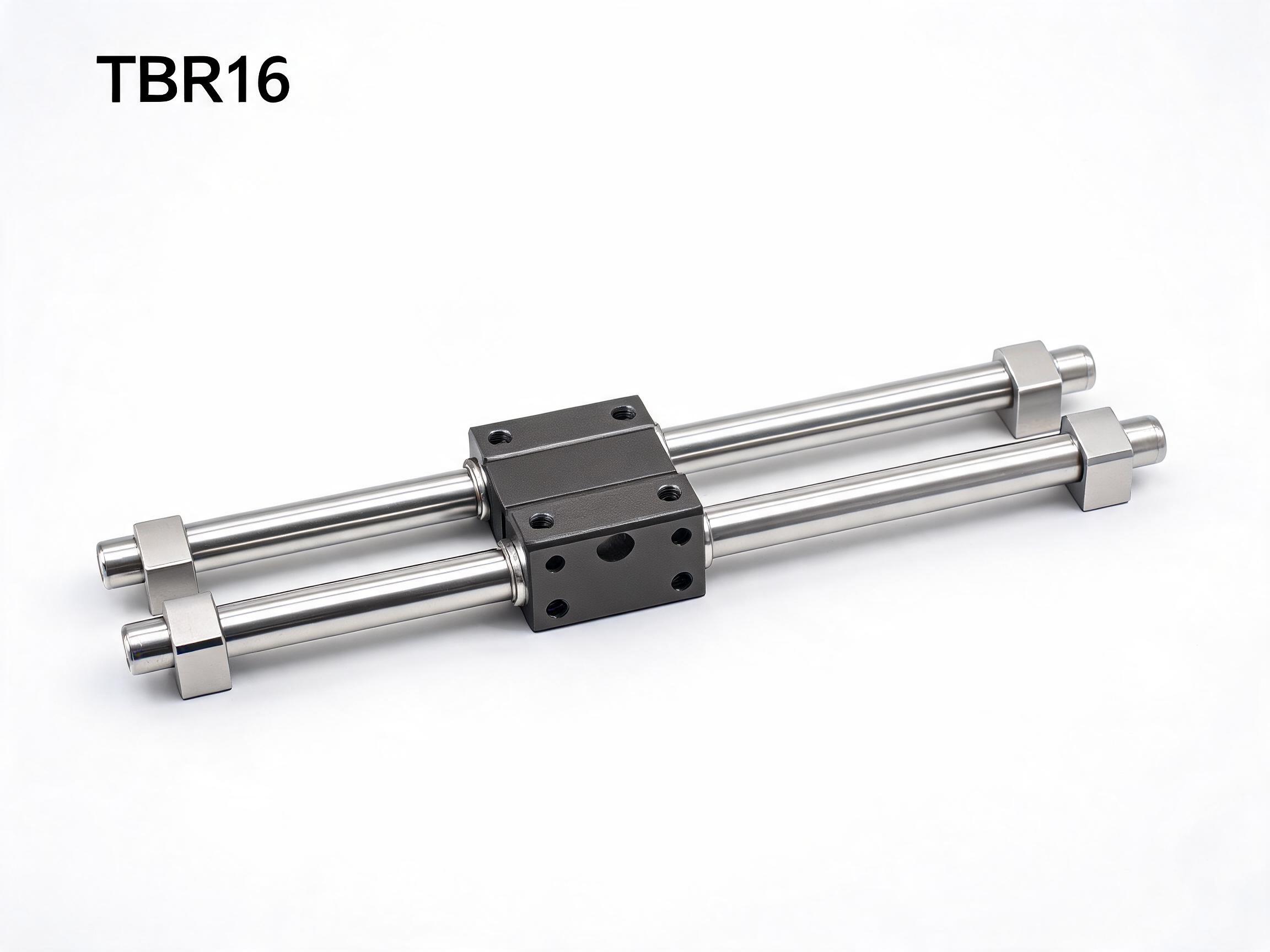
Two independent round-rail units on a cantilever or pick-and-place axis each find their own path under load, and the housing that spans them has to absorb the difference. This article explains how a synchronized dual-shaft linear motion system built on 16 mm shafts solves that mismatch, where the two-shaft arrangement earns its space, and how shaft spacing and length shape the decision.
Axis architecture
Build a cantilever head or pick-and-place axis from two single-shaft round-rail units and the two carriages will not sit with identical friction. Something has to give, and it is usually the yaw. A synchronized TBR16 dual-shaft guide puts one carriage housing across both 16 mm shafts so the axis can only move in one direction.
Where two single-shaft units start to disagree
Two single-shaft round-rail units are a reasonable starting point when the load is light and the span is short. Mount a carriage on each shaft, bolt a plate across the two carriages, and the plate now bridges two separate motion systems. Nothing in that arrangement forces the two carriages to travel as one axis.
In practice they do not. Each unit has its own bearing block, its own preload setting and its own friction. Under a cantilever load, the near carriage carries more stress than the far one, so the load distribution shifts and the two carriages move at slightly different rates. The plate bridging them is rigid, so the difference turns into yaw: the tool plate rotates slightly around the vertical axis. Push harder and the misalignment shows up as binding, uneven wear or a control loop that keeps stalling on the same move.
An assembly engineer can spend a lot of time shimming and re-aligning two independent units to chase this. The friction mismatch itself is not really a shim problem, and it returns as the bearings wear in.
What the synchronized carriage changes
A TBR16 synchronized dual-shaft linear motion guide system does not bridge two separate carriages. It uses a single synchronized carriage housing that spans two parallel 16 mm shafts. The housing is one part, so both shaft positions are fixed relative to each other by the carriage itself, not by a plate bolted between two independent units.
The effect on the axis is direct:
- Yaw is held by the single housing. There is no second carriage with its own clearance to take up.
- There is no friction mismatch to cancel, because there is only one carriage travelling on two shafts.
- The binding that comes from two slightly different preloads does not arise, since both shafts are guided by the same set of bearing paths.
The shafts themselves are 16 mm GCr15 chrome steel hardened to HRC 58-62. They run on two anodized aluminum 6063-T5 support rails, and those rails share mounting holes so the whole system bolts onto a single flat surface. That last point matters on a cantilever axis: the two rail positions are set by the rail pair, not by how well an installer can measure two separate mounting footprints.
The moment-load reason for two shafts
A single-shaft unit carries its load on one shaft line. A cantilevered pick-and-place head, a tool changer or a Z-axis assembly puts a moment on the carriage, and a moment has to be resisted by distance. Two shafts give that distance.
The dual-shaft arrangement resists pitch and yaw moment loads because the two shaft lines are separated by the shaft center distance. On a Z-axis with an offset tool, or on a head that reaches out from the carriage, that separation is what keeps the plate from tipping around the shaft. A single-shaft unit has no such lever to work with.
The published load figures for the TBR16 carriage are:
| Parameter | Value |
|---|---|
| Dynamic load | 15.6 kN per carriage (7.8 kN x 2 shafts) |
| Static load | 24.0 kN |
| Shaft diameter | 16 mm |
| Shaft material | GCr15 chrome steel, HRC 58-62 |
| Carriage mounting | 4x M6 top-face bolts |
| System height | Under 30 mm |
The dynamic figure is stated per carriage and already reflects both shafts. If you are comparing it against a pair of single-shaft units, compare like with like: the dual-shaft number covers the whole synchronized carriage, not one rail of it.
Choosing shaft center distance
Shaft center distance is the main sizing decision once the load is known. The TBR16 is available at standard 60 mm, 80 mm or 100 mm center distance. Custom spacing is possible with a higher minimum order quantity.
The choice comes down to the moment arm you need to resist and the space the head has to fit into:
- A short offset or a compact Z-axis is usually served by the 60 mm standard spacing.
- A cantilevered head that reaches further from the carriage needs more separation, which points toward 80 mm or 100 mm.
- If the machine envelope allows neither standard, custom spacing is the route, and that changes the order quantity rather than the shaft length.
Larger spacing raises the resisting moment but also widens the mounting footprint and adds a little to the moving mass. It is a trade, not a free upgrade, and the right value depends on where the load actually sits relative to the carriage center.
Length, alignment and what to check on the drawing
Standard maximum length is 2000 mm, with custom lengths up to 3000 mm. Long axes are where parallelism matters most, because a small angular error over a long span becomes a large positional error at the end of the stroke.
Shaft parallelism for this system is verified on a dedicated alignment jig to within 0.02 mm over 1000 mm of length, from factory verification data. That figure describes the shaft pair as supplied. It does not describe what happens after the rails are bolted to a machine bed that is not flat, which is why the shared mounting holes on the support rails are worth using as intended: one flat surface, one footprint.
Before ordering, confirm three things against your own design:
- That the mounting surface the rails will sit on is flat enough for the axis length you have chosen.
- That the shaft center distance clears the surrounding structure through the full stroke, not only at mid-travel.
- That the 4x M6 top-face carriage bolts carry the plate in the orientation your head needs.
When two separate units are still the right call
The synchronized dual-shaft system is not a universal replacement for separate round-rail units. There are cases where two independent single-shaft units remain simpler: wide, lightly loaded transfer axes where the two rails sit far apart and each carries its own carriage rather than a shared plate, or applications where the rails must follow different mounting planes.
For a single-shaft reference point, the SBR16 linear motion guide rail unit with bearing block shows the alternative architecture: one rail, one block, one shaft line taking the load. Where the moment is small and the head is balanced over the bearing, that is enough. Where the head cantilevers and yaw would show up in the work, the single-shaft line has no second shaft to resist it.
The decision question is not round rail versus profile rail. It is whether the load path passes through one shaft line or two, and whether the two are mechanically tied together by the carriage.
Ordering and configuration notes
The TBR16 system is supplied as a set of two rails plus one synchronized carriage. The minimum order quantity is 30 sets. Custom shaft spacing carries a minimum order quantity of 50 sets, which is worth planning for early if a standard 60 mm, 80 mm or 100 mm distance does not fit your head design.
Because the carriage housing fixes the shaft relationship, the center distance and the length are set together when the set is built. Changing either after the fact means a new set, not a field adjustment, so lock both into the drawing before releasing the order.
Can I use a TBR16 carriage on two shafts I source separately?
No. The carriage housing is machined for a specific shaft center distance. The synchronized motion depends on that matched pair.
Does the 0.02 mm parallelism figure apply after installation?
It is a factory verification of the shaft pair on an alignment jig. Final axis accuracy depends on the flatness of the surface the support rails are mounted to.
How much load does one carriage take?
15.6 kN dynamic per carriage, which is the combined figure for the two shafts, and 24.0 kN static.
How long can the shafts be?
Standard maximum is 2000 mm. Custom lengths reach 3000 mm.
What to send with an enquiry
An enquiry for this kind of axis resolves fastest with four pieces of information: the stroke length, the load and its offset from the carriage center, the shaft center distance your head design can accept, and the orientation of the carriage mounting plate. With those, the question of standard versus custom spacing is usually settled in one exchange.