
A step-by-step guide to converting required thrust and lead into drive torque, with the governing formula, variable definitions, a worked example, and the two errors that most often throw off the result.
Engineering calculation
A ball screw converts rotary motor motion into linear thrust. When specifying one, buyers and machine builders need the reverse of that relationship: how much torque the motor must deliver to push or pull a defined load through the screw. This article gives the working formula, defines every variable with its unit, walks through one complete calculation, and explains the two mistakes that most often produce an undersized motor or an oversized one.
Key takeaways
- Drive torque rises with thrust and lead, and falls as screw efficiency rises.
- Thrust is the total linear force at the load, not the load weight alone.
- Lead must be entered in meters, not millimeters.
- Efficiency must come from the manufacturer's datasheet, not from a memory of "around 90 percent."
The governing formula
The relationship between linear thrust and rotary torque for a ball screw is a direct expression of work done: the linear force moving through one lead must equal the rotary torque times the angle swept, minus losses inside the screw. Written out:
This form is what most selection tools and drive-sizing worksheets use. Some references add a preload or drag term, and a full drive train also has motor and coupling inertia. This formula answers one specific question: what steady-state torque is required to hold or move a defined thrust through a screw of given lead and efficiency.
What each variable means and its unit
| Symbol | Variable | Meaning at the machine | Unit |
|---|---|---|---|
| T | Drive torque | Torque the screw must receive to produce the thrust; the motor or gearbox output must meet or exceed this | newton-meter (N·m) |
| F | Thrust | Total axial force the load requires, including gravity components, friction and any process force | newton (N) |
| L | Lead | Axial distance the nut travels per one revolution of the screw | meter (m) |
| η | Efficiency | Fraction of input work delivered as linear push, from the ball screw datasheet | dimensionless (0 to 1) |
| 2π | Full revolution | Radians swept in one turn of the screw | radian (rad) |
A worked example
Take a horizontal axis that must produce a thrust of 5000 N. The selected ball screw has a lead of 10 mm, and the datasheet gives an efficiency of 0.90 for the assembly. Convert the lead to meters before substituting anything: 10 mm equals 0.010 m. Then apply the formula:
T = 5000 × 0.010 / (2π × 0.90) ≈ 8.8 N·m
The result is roughly 8.8 N·m of torque at the screw, which is the figure a motor or gearbox must supply at the screw input shaft. The intermediate step is worth writing down explicitly, because the arithmetic is simple but the units are where errors enter:
- Numerator: 5000 N × 0.010 m gives the linear work per revolution in joule terms.
- Denominator: 2π × 0.90 converts that work into the torque needed at the screw, after allowing for the loss in traveling from rotary to linear motion.
Common error 1: forgetting efficiency
A screw cannot return all of the rotary work as linear push. Some of it is absorbed in ball circulation, contact deformation and lubrication drag. Dropping the η term from the formula returns 5000 × 0.010 / (2π) ≈ 8.0 N·m, which is smaller than the 8.8 N·m above: dividing by the full 2π instead of 2π × 0.90 hides the losses and produces an optimistic number. The error works both ways.
When the engineer omits efficiency, the torque figure no longer represents the screw. If the supplier's assembly has a lower efficiency than assumed, the motor calculated without the loss term will stall or overheat under continuous load. If the buyer instead plugs in an efficiency that is too low, they over-specify the motor, gearbox and coupling, and pay for frame size and inertia they never needed. The efficiency figure is a mechanical property of the specific screw assembly, and it belongs in the calculation exactly as the datasheet publishes it.
Two practical checks follow from this. First, the efficiency belongs to the complete assembly, nut and screw together, not to a generic "ball screw" category. Second, if the datasheet does not state an efficiency for the assembly you intend to buy, ask the supplier to confirm it before the motor is ordered, and record the value used in the calculation sheet.
Common error 2: unit conversion
Lead is routinely quoted in millimeters on catalogs and drawings, and just as routinely typed into the formula in millimeters. The formula's π and length are consistent only when the length is in meters. A lead entered as 10 instead of 0.010 inflates the result enormously, because the torque figure is scaled by a factor of one thousand.
The reverse mistake appears when thrust is expressed in kilograms-force and left unconverted to newtons. A force value in the wrong unit cannot be mixed with SI lengths and still produce a newton-meter torque.
A simple rule keeps the calculation clean: write every input in SI base units before substituting, then convert the answer only for presentation. Thrust in newtons, lead in meters, efficiency as a decimal fraction, torque in newton-meters. If a drawing gives the lead in millimeters, convert it in the same line where it is entered, so the conversion cannot be forgotten later.
Defining the thrust correctly
Most of the error in a torque calculation actually happens before the formula is applied. The thrust term F is not the mass of the moving load; it is the total axial force the screw must develop at the nut. For a horizontal axis that carries a load on a guide, thrust must overcome the friction of the guide and any working resistance such as cutting force, spring force or the force needed to compress a product. For a vertical axis, the load weight acts along the screw axis and enters the thrust term directly, and the calculation should be done for the worst direction of travel.
Work through the force balance first, in the same units, and write down every contributor. Only then apply the torque formula. A correctly computed torque from an incomplete force list is still wrong for the machine.
From screw torque to the motor
The result T is the torque required at the screw. How that reaches the motor depends on the drive arrangement. A directly coupled motor must deliver T at its shaft. A motor through a reduction gearbox needs a smaller output torque, in proportion to the reduction, with the gearbox's own efficiency accounted separately. A belt or pulley drive introduces its own ratio and loss.
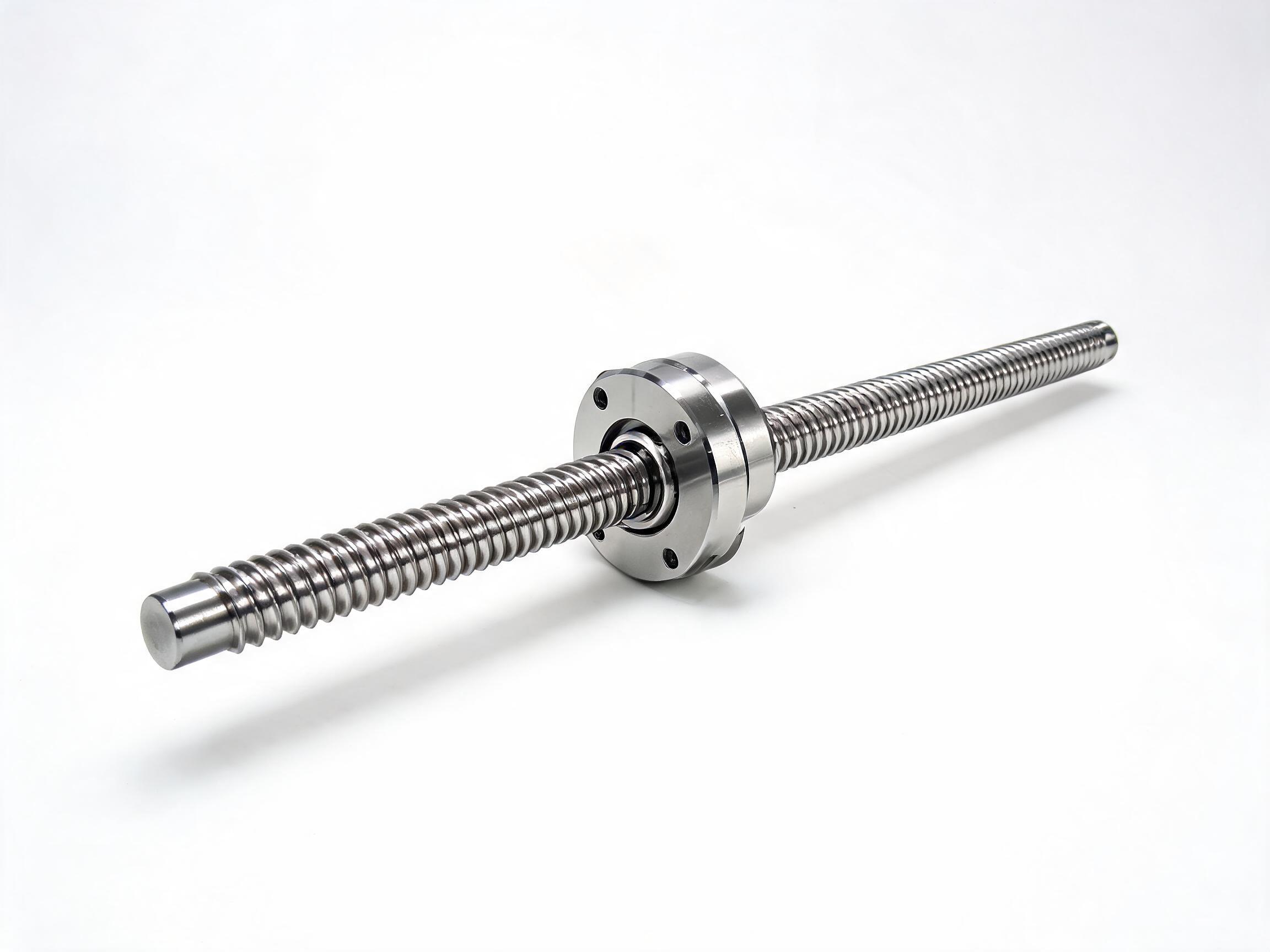
Where a nut drives a rotating screw, or where the screw rotates and the nut travels, the axial force and torque relationship is the same; only the location of the motor changes. That is why the formula is written in terms of thrust, lead and efficiency only. Whether the application calls for a flange-nut assembly or a screw with a specific end configuration is a mechanical fit decision, and it sits alongside the torque calculation rather than inside it.
What to record before ordering
- Maximum thrust the axis must produce, with the force contributions itemized.
- Lead in meters, converted from the drawing value.
- Efficiency for the exact screw assembly, taken from its datasheet.
- Drive arrangement, including any reduction ratio and its efficiency.
- The resulting torque at the screw, and the torque the chosen motor must deliver at its own shaft.
With these five items written down, a torque calculation can be checked by a second person without re-deriving anything. That is the point of keeping the calculation explicit: it becomes an auditable record of how the motor size was chosen, and when the load or the screw changes, only the changed inputs need to be revisited.
Ball screw assemblies with different nut configurations are listed here: SFU2510 rolled ball screw assembly with flange nut and the wider SFU series rolled ball screw assembly range. Datasheet efficiency values for a specific assembly should be confirmed with the supplier before the motor torque is finalized.