
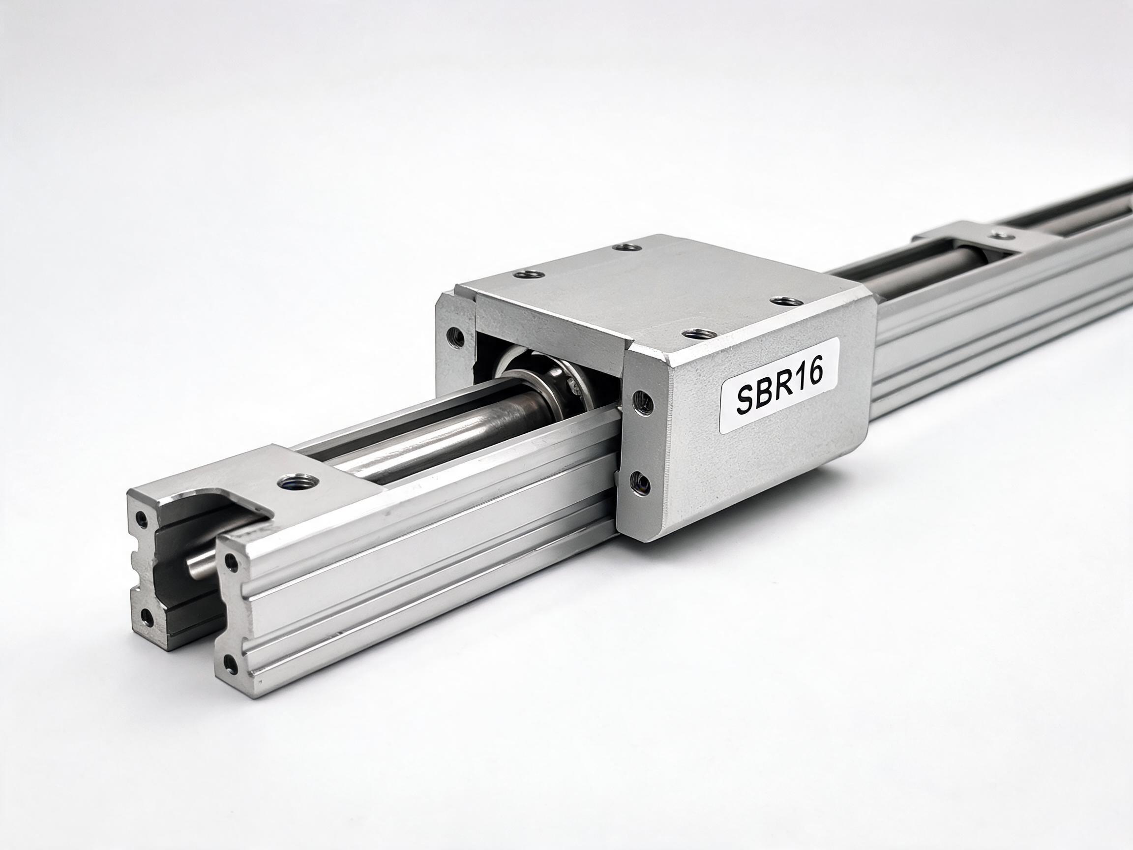
A practical comparison of SBR and TBR linear bearing slide rail systems — covering load capacity, shaft hardness, alignment tolerance, mounting differences, and selection criteria for automation builders. Includes a spec comparison table, integration steps, and common mistakes to avoid.
AUTOMATION BUYER GUIDE
When you are building a linear motion axis for a pick-and-place machine, a packaging line, or a custom assembly station, the choice between SBR and TBR linear bearing slide rail systems is one of the first decisions you will make. Both are widely used in automation, but they are not interchangeable. They differ in shaft hardness, load capacity, alignment tolerance, and mounting method — and picking the wrong one shows up later as noise, premature wear, or a seized carriage. This guide covers the practical differences, the selection criteria, and the integration steps an automation builder needs before sending out a request for quotation.
Key takeaways
- SBR rails use chrome-plated shafting with a flat mounting base; TBR rails use fully supported, hardened shafting with a rectangular rail profile.
- TBR systems carry higher loads and run smoother at speed, but require better base flatness and more precise alignment.
- SBR is the lower-cost option for light-duty, short-stroke applications; TBR suits medium-to-heavy loads and longer strokes.
- Shaft hardness, straightness, and support block spacing determine real-world service life more than the bearing size alone.
- Confirm mounting surface flatness and parallelism with the supplier before finalizing the rail specification.
What Is a Linear Bearing Slide Rail System?
A linear bearing slide rail system consists of a hardened and ground shaft (the rail) and a linear bearing block that travels along it. The block contains recirculating balls that roll between the shaft and the block raceways, converting rolling motion into low-friction linear travel. The two most common round-rail configurations in automation are:- SBR series — the rail is a chrome-plated shaft mounted on a flat aluminum support base. The base provides the mounting surface; the shaft sits on top of it.
- TBR series — the rail is a fully supported round shaft with a rectangular cross-section base. The shaft is integrated into the rail profile, giving higher rigidity and load capacity.
SBR vs TBR: The Core Differences
SBR Linear Slide Rail Systems
SBR rails are built around a chrome-plated shaft with a hardness of approximately HRC 60–62 on the surface. The shaft is pressed or mounted onto an aluminum base with a flat bottom, which bolts directly to your machine frame. Typical SBR characteristics:- Shaft diameter range: commonly 8 mm to 50 mm
- Load capacity: light to medium — suitable for positioning tables, conveyor guides, and light pick-and-place gantries
- Mounting: flat base with through-holes; shimming is often used to correct minor misalignment
- Cost: lower than TBR for the same shaft diameter
- Speed: moderate; best for short strokes and lower cycle rates
TBR Linear Slide Rail Systems
TBR rails use a fully supported shaft with a rectangular steel rail body. The shaft is ground and hardened as part of the rail profile, and the entire assembly is stiffer than an SBR rail of the same diameter. Typical TBR characteristics:- Shaft diameter range: commonly 8 mm to 50 mm
- Load capacity: medium to heavy — suitable for machining fixtures, heavier gantries, and higher-speed transfer axes
- Mounting: rectangular base with counterbored holes; requires a flatter, more precise mounting surface
- Cost: higher than SBR for the same shaft diameter
- Speed: higher; runs smoother with less vibration at speed
| Parameter | SBR Series | TBR Series |
|---|---|---|
| Rail construction | Chrome-plated shaft on aluminum base | Integrated hardened shaft on steel rail |
| Shaft hardness | ~HRC 60–62 surface | ~HRC 60–62 surface |
| Typical shaft diameter | 8 – 50 mm | 8 – 50 mm |
| Load capacity | Light to medium | Medium to heavy |
| Rigidity | Moderate; shaft separate from base | High; shaft integrated into rail |
| Mounting surface requirement | Moderate flatness; shimming acceptable | Good flatness; precise alignment required |
| Typical speed | Low to moderate | Moderate to high |
| Relative cost | Lower | Higher |
| Common applications | Light gantries, conveyors, positioning tables | Heavier gantries, transfer axes, machining fixtures |
How to Choose Between SBR and TBR
The decision is not about which is "better." It is about which fits the load, speed, stroke, and mounting conditions of your specific axis.Choose SBR when:
- The payload is light to medium (typically under a few hundred kilograms, depending on shaft diameter and number of bearings)
- Stroke length is short to moderate (under about 1.5–2 meters)
- Cycle rates are low to moderate
- The mounting surface is not perfectly flat, and you want the option to shim during installation
- Budget is a primary constraint
Choose TBR when:
- The payload is heavier or the load is offset from the rail centerline
- Stroke length is longer and deflection must be minimized
- The axis runs at higher speed and needs smooth, low-vibration travel
- The machine frame is rigid and the mounting surface is machined flat
- You need higher stiffness for consistent positioning accuracy
A common rule of thumb: if you are unsure whether the application is "light" or "heavy," calculate the dynamic load on the worst-positioned bearing and compare it against the bearing's dynamic load rating (C value). If the applied load exceeds 30–40% of the C value, move up a shaft size or switch to TBR.
Integration Steps for Automation Builders
Step 1: Define the Axis Requirements
Write down the numbers before you talk to a supplier:- Payload mass (kg) and center of gravity location
- Stroke length (mm)
- Travel speed and acceleration (m/s and m/s²)
- Cycle rate (strokes per minute)
- Required positioning accuracy and repeatability
- Environmental factors (dust, humidity, temperature, washdown)
Step 2: Calculate the Load on Each Bearing
For a horizontal axis with two rails and four bearings, the load is not evenly distributed. The bearing closest to the load center takes the most force. Use the dynamic load rating (C) from the bearing datasheet and apply a safety factor of 2–3 for dynamic applications. If the calculated load on any single bearing exceeds about 30–40% of its C value, the bearing will have a short service life. Move to a larger shaft diameter or add more bearings.Step 3: Check the Mounting Surface
SBR rails tolerate moderate base flatness because the aluminum base can be shimmed. TBR rails need a flatter surface — typically within 0.05 mm over the rail length for longer axes. If your frame is welded steel without machining, SBR is the safer choice. If the frame is machined aluminum or cast iron, TBR is viable.Step 4: Select the Bearing Block Type
Both SBR and TBR systems use open or closed bearing blocks:- Closed blocks (SC, TMC) — standard for most applications; the block fully encloses the shaft
- Open blocks (SC…UU, TMC…UU) — used when a shaft support is needed along the travel path or when the shaft must pass through a wall
Step 5: Verify Shaft Straightness and Hardness
Shaft straightness is typically specified as 0.05 mm per 1000 mm for standard grades, with higher grades available. Surface hardness should be at least HRC 58–62 for the bearing balls to roll without brinelling the shaft. Ask the supplier for the hardness test report and straightness certificate if the application requires it.Step 6: Plan for Lubrication and Seals
Linear bearings need lubrication. Most blocks come with a grease fitting (oil nipple) and a felt or rubber seal. For dusty environments, specify double seals. For washdown or food-grade applications, confirm the lubricant compatibility with the seals and the application environment.Common Integration Mistakes
Mistake 1: Oversizing the Bearing, Undersizing the Rail Support
A larger bearing block does not fix a rail that flexes under load. The rail support structure — the base for SBR or the rail profile for TBR — determines deflection. If the rail bends, the bearing balls lose contact with the raceway, and the block wears unevenly.Mistake 2: Ignoring Parallelism Between Two Rails
When you mount two parallel rails, the distance between them must be consistent along the full stroke. If the rails are not parallel, the carriage binds, and the bearings wear quickly. For TBR rails, this is critical — the stiffness that gives TBR its load capacity also makes it unforgiving of misalignment.Mistake 3: Forgetting Thermal Expansion
On long axes (over 1.5 meters), temperature changes cause the rail to expand. If both ends are rigidly fixed, the rail can buckle or the bearings can preload excessively. Use a fixed-floating mounting arrangement — rigidly fix one end, allow the other end to float axially.Mistake 4: Choosing SBR for a High-Speed Axis
SBR rails with a separate shaft and aluminum base are more flexible than TBR rails. At higher speeds, this flexibility causes vibration and noise, and the carriage can lose contact with the shaft. If your axis runs above about 1 m/s with moderate loads, TBR is the safer choice.Cost Considerations
SBR systems are generally 20–40% cheaper than TBR systems for the same shaft diameter. But the cost difference narrows when you account for installation:- SBR installation is more forgiving — you can shim the base to correct minor surface errors, which saves machining time
- TBR installation requires a flatter mounting surface, which may mean an extra machining pass on the frame
FAQ
Can I use SBR bearings on a TBR rail?
No. The bearing block and rail must match. SBR bearings (SC series) are designed for the SBR shaft-on-base profile. TBR bearings (TMC series) match the TBR rail profile. Mixing them will not fit or will fail quickly.What is the maximum stroke length for SBR rails?
SBR rails are commonly available up to about 3000 mm, but for strokes above 1500–2000 mm, deflection becomes a concern. For longer strokes with medium loads, TBR is the safer choice. Confirm the straightness and support spacing with the supplier.Do I need to preload the bearings?
Standard linear bearings have a small internal clearance. For applications requiring higher rigidity, some suppliers offer preloaded blocks. Preload increases stiffness but also increases friction and wear. It is not needed for most light-duty positioning applications.How do I specify the right shaft diameter?
Start with the load calculation. For a horizontal axis with four bearings and a centered load, a 20 mm shaft handles roughly 300–500 kg static load per bearing, but the dynamic rating is much lower. Use the dynamic load rating (C) and a safety factor of 2–3. When in doubt, move up one shaft size — the cost increase is small compared to the cost of a failed axis.Next Steps
Before you send a request for quotation, prepare the following:- Axis load, speed, stroke, and cycle rate
- Mounting surface condition (flatness, material, machining status)
- Environmental requirements (dust, washdown, temperature)
- Preferred shaft diameter and rail series (SBR or TBR)
- Bearing block type (closed or open) and seal requirement