
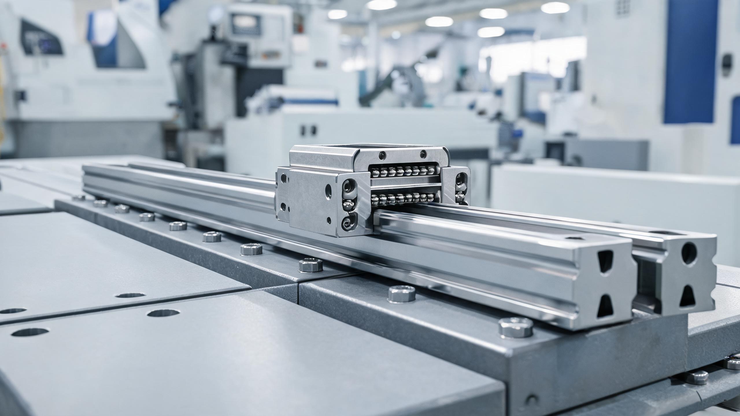
A practical engineering guide for CNC builders and maintenance teams. Covers how to evaluate rigidity in heavy duty linear guide rails, how to select preload classes for different machining conditions, and how to integrate heavy duty linear slide rails into machine tool assemblies correctly.
BUYER & ENGINEERING GUIDE
Heavy Duty Linear Guide Rail for CNC: Rigidity, Preload Selection, and Machine Tool Integration Guide
If you are building or retrofitting a CNC machine, the linear guide rail is not a commodity part. It is the structural interface between the cutting force and the machined surface. A poorly selected heavy duty linear guide rail shows up immediately as chatter marks, poor surface finish, and shortened ball screw life.
This guide covers three decisions that matter most when specifying a cnc linear guide rail for machine tool duty: how to evaluate rigidity, how to choose the correct preload class, and how to integrate the rail into the machine base without introducing errors.
- Rigidity is a system property — rail size, mounting surface stiffness, and preload all contribute. Do not spec the rail in isolation.
- Preload class is a trade-off between stiffness and heat generation. Heavy cutting wants more preload; high-speed finishing wants less.
- Mounting surface flatness and bolt torque are where most field failures originate. A good rail on a bad surface performs like a bad rail.
Why Standard Linear Guides Fail in CNC Duty
A standard linear guide is designed for positioning accuracy at moderate loads. A CNC machine tool operates under different conditions: intermittent heavy cutting loads, vibration from the spindle, and continuous duty cycles.
The failure modes are specific:
- Deflection under load — the carriage tilts, the table loses geometric accuracy, and the tool path drifts.
- Premature wear — insufficient preload allows ball skidding, which generates heat and flattens the raceway.
- Loss of preload over time — soft mounting surfaces deform, and the original interference fit disappears.
A heavy duty linear slide rail addresses these by using larger ball diameters, more load-carrying balls per circuit, and a deeper, hardened raceway. But bigger is not automatically better. The rail must match the machine's stiffness envelope.
Rigidity: What Actually Determines It
Rigidity in a linear guide is the resistance to elastic deformation under load. It is measured in N/µm — the force required to produce one micron of deflection. Higher is stiffer.
Four factors determine the rigidity you actually get:
1. Rail cross-section and size. A wider rail with a taller profile has a higher moment of inertia. For the same material, a 35 mm rail is noticeably stiffer than a 25 mm rail. The dynamic load rating (C value) is a useful proxy, but the static moment ratings tell you more about rigidity under off-center loads.
2. Number and arrangement of load-carrying balls. More contact points distribute the load. Four-row designs (two rows at 45° contact angles each side) are standard for heavy duty linear guide rails because they handle radial, reverse radial, and moment loads in all directions.
3. Preload. Preload removes internal clearance and puts the balls in a slight interference fit with the raceway. This eliminates the "dead zone" where the carriage moves before the balls actually engage. Higher preload = higher rigidity, up to the point where heat generation becomes the limiting factor.
4. Mounting surface stiffness. This is the one most buyers overlook. A rail bolted to a thin sheet metal base will flex regardless of how stiff the rail itself is. The base must be thick enough, and ideally ribbed, to provide a rigid foundation.
| Rail Size (mm) | Typical Dynamic Load C (kN) | Typical Static Moment Mx (kN·m) | Typical Application |
|---|---|---|---|
| 25 | 17 – 25 | 0.2 – 0.3 | Light milling, drilling, small gantry |
| 30 | 28 – 38 | 0.4 – 0.6 | Medium machining centers, EDM |
| 35 | 45 – 60 | 0.8 – 1.1 | Heavy milling, CNC lathes, machining centers |
| 45 | 70 – 90 | 1.5 – 2.0 | Large gantries, heavy-duty machining centers |
| 55 | 100 – 140 | 2.8 – 3.8 | Bridge mills, heavy-duty planing machines |
Typical values for standard heavy duty linear slide rails. Exact ratings depend on the manufacturer's internal geometry and ball size — always confirm against the specific product datasheet.
Preload Selection: The Stiffness vs. Heat Trade-off
Preload is the internal force applied between the balls and raceways, eliminating clearance. It is classified by the amount of interference, typically expressed as a percentage of the dynamic load rating or as a clearance class (C0, C1, C2, C3).
For cnc linear guide rail applications, the common classes are:
- C0 (light preload / zero clearance): Minimal or no preload. Used where friction must be minimal and loads are light and predictable. Not recommended for machining.
- C1 (light preload): Small interference. Good for high-speed, light-cut applications where heat must be minimized. Suitable for precision measurement machines, not for heavy material removal.
- C2 (medium preload): The default for most CNC applications. Provides a good balance of rigidity and acceptable heat generation. Suitable for general milling, turning, and drilling.
- C3 (heavy preload): Maximum rigidity. Used for heavy cutting, intermittent loads, and where vibration resistance is critical. Generates more heat and requires proper lubrication.
The selection logic is straightforward:
- Heavy roughing, interrupted cuts, hard materials → C3 or C2. The rigidity prevents chatter and maintains tool life.
- General machining, mixed operations → C2. The safe default.
- High-speed finishing, light cuts, precision grinding → C1. Minimizes heat and stick-slip.
- Never use C0 in a cutting machine. The clearance allows the table to move under load, causing poor finish and accelerated wear.
A common field mistake is specifying the highest preload "for safety." Heavy preload on a small rail in a high-speed application generates excessive heat, which expands the balls, increases preload further, and leads to premature failure. Match preload to the actual cutting regime.
Integration into the Machine Tool: Mounting, Alignment, and Torque
A heavy duty linear slide rail performs only as well as its installation. The following points are the most common sources of field problems.
1. Mounting Surface Preparation
The mounting surface must be machined flat. Typical specification is 5–10 µm flatness over the rail length, depending on rail size. The surface should also be free of burrs, rust, and debris.
If the base is a welded fabrication, stress-relieve it before machining. Otherwise, the weld distortion will pull the rail out of alignment over time.
2. Reference Edge
Use the machined side edge of the base as the reference. The rail's side face is ground to a precise dimension from the raceway. Push the rail against this reference edge during bolt tightening.
Do not rely on the bolt holes for alignment — they have clearance and will not center the rail.
3. Bolt Torque and Sequence
Tighten bolts in a sequence that progresses from the center outward, in stages. First pass at 30% of final torque, second pass at 70%, final pass at 100%. This prevents the rail from bowing.
Torque values are specified by the rail manufacturer based on bolt size and material. Use a calibrated torque wrench. Under-torquing allows movement; over-torquing distorts the rail.
| Bolt Size | Typical Torque (N·m) | Bolt Grade |
|---|---|---|
| M6 | 10 – 12 | 12.9 |
| M8 | 24 – 28 | 12.9 |
| M10 | 48 – 55 | 12.9 |
| M12 | 85 – 95 | 12.9 |
Indicative values. Always follow the rail manufacturer's specific torque specification for the exact bolt and rail combination.
4. Parallelism of Two Rails
For a two-rail system, the rails must be parallel within a few microns over their length. Use a straight edge and feeler gauge, or a dial indicator on a reference block, to check.
If the rails are not parallel, the carriage will bind, preload will increase unevenly, and the drive motor will work harder — leading to premature wear of both the rails and the ball screw.
5. Lubrication
Heavy duty linear guide rails in CNC duty require automatic lubrication. Grease fittings on the carriage should be connected to a central lubrication system. Use a grease compatible with the operating temperature range.
For high-speed applications, consider oil lubrication instead of grease, as oil dissipates heat more effectively.
Common Specification Mistakes to Avoid
Mistake 1: Oversizing the rail "for safety." A 45 mm rail on a machine that needs 30 mm adds weight, cost, and friction. The extra rigidity may not be needed, and the higher friction generates more heat. Size the rail to the actual cutting forces and required stiffness.
Mistake 2: Ignoring moment loads. A gantry or a spindle head mounted off-center creates moment loads (pitch, roll, yaw) that the rail must resist. Check the static moment ratings (Mx, My, Mz) against your actual load distribution, not just the vertical load.
Mistake 3: Mixing preload classes on the same axis. Both rails on one axis should have the same preload. Mixing C1 and C3 on the same axis creates uneven stiffness and causes the table to skew under load.
Mistake 4: Forgetting the ball screw alignment. The ball screw must be parallel to the guide rails within tight tolerances. Misalignment between the screw and the rails creates side loads on both components, reducing life significantly.
How to Evaluate a Supplier for Heavy Duty Linear Guide Rails
When sourcing a heavy duty linear guide rail from a manufacturer, ask for specific technical documentation:
- Dimension and tolerance drawings — confirm the mounting dimensions and the accuracy grade (e.g., JIS C, H, P classes).
- Dynamic and static load ratings — verify the C and C0 values for the exact rail size you need.
- Moment ratings — Mx, My, Mz values for your load case.
- Preload class definitions — confirm how the manufacturer defines each class and what the corresponding rigidity values are.
- Material and hardness data — typically bearing steel (e.g., GCr15 / SUJ2) with raceway hardness around HRC 58–62.
- Surface treatment options — for corrosive environments, ask about chrome plating or other protective coatings. Note that plating can affect dimensional accuracy, so confirm tolerances after treatment.
A reliable supplier should provide this data without hesitation. If a manufacturer cannot supply load ratings and tolerance data, that is a red flag.
FAQ
Q: What is the difference between a heavy duty linear guide rail and a standard one? A: Heavy duty rails use larger balls, more load-carrying circuits, and deeper hardened raceways. They have higher load ratings and higher rigidity for the same rail size. Standard rails are for lighter positioning applications.
Q: How do I know if my mounting surface is stiff enough? A: As a rule of thumb, the mounting surface should be at least as stiff as the rail itself. If you can deflect the surface with hand pressure, it is too thin. For a 35 mm rail, the mounting base should typically be at least 20–30 mm thick, with ribs where possible.
Q: Can I use a heavy preload rail for high-speed finishing? A: Technically yes, but you will generate more heat and may see thermal expansion issues. For high-speed finishing, a medium preload (C2) is usually the better choice. If you need both heavy cutting and high-speed finishing on the same machine, consider a C2 preload as the compromise.
Q: How often should I lubricate a CNC linear guide rail? A: In continuous CNC duty, automatic lubrication every few hours of operation is typical. The exact interval depends on the duty cycle, speed, and ambient conditions. Monitor the grease condition — if it darkens or contains metal particles, check for wear or contamination.
Q: What accuracy grade do I need for a CNC machine? A: For general CNC machining, JIS C grade (normal) is often sufficient. For precision grinding or high-accuracy machining, use H grade. P grade (precision) is for very high accuracy applications like coordinate measuring machines. Higher accuracy grades cost more, so match the grade to the machine's actual requirements.
Final Recommendations
Specifying a heavy duty linear guide rail for a CNC machine is a systems engineering task. Start with the cutting forces and required accuracy, then work backward to rail size, preload, and mounting design.
For most general-purpose CNC machining centers, a C2 preload with a rail size matched to the machine's weight class is a solid starting point. For heavy roughing or interrupted cuts, step up to C3. For high-speed finishing machines, consider C1.
Do not treat the rail as an isolated component. The mounting surface, bolt torque, alignment, and lubrication are all part of the system. A good rail on a poorly prepared base will fail prematurely.
If you are specifying a custom machine or retrofitting an existing one, send your load conditions and mounting dimensions to the supplier. Most reputable manufacturers will help you select the correct rail size and preload class for your specific application. The data is available — use it.
Need help selecting the right heavy duty linear guide rail for your CNC project? Contact us with your machine specifications, cutting forces, and mounting dimensions. We will recommend a rail size, preload class, and accuracy grade based on your actual application requirements.