
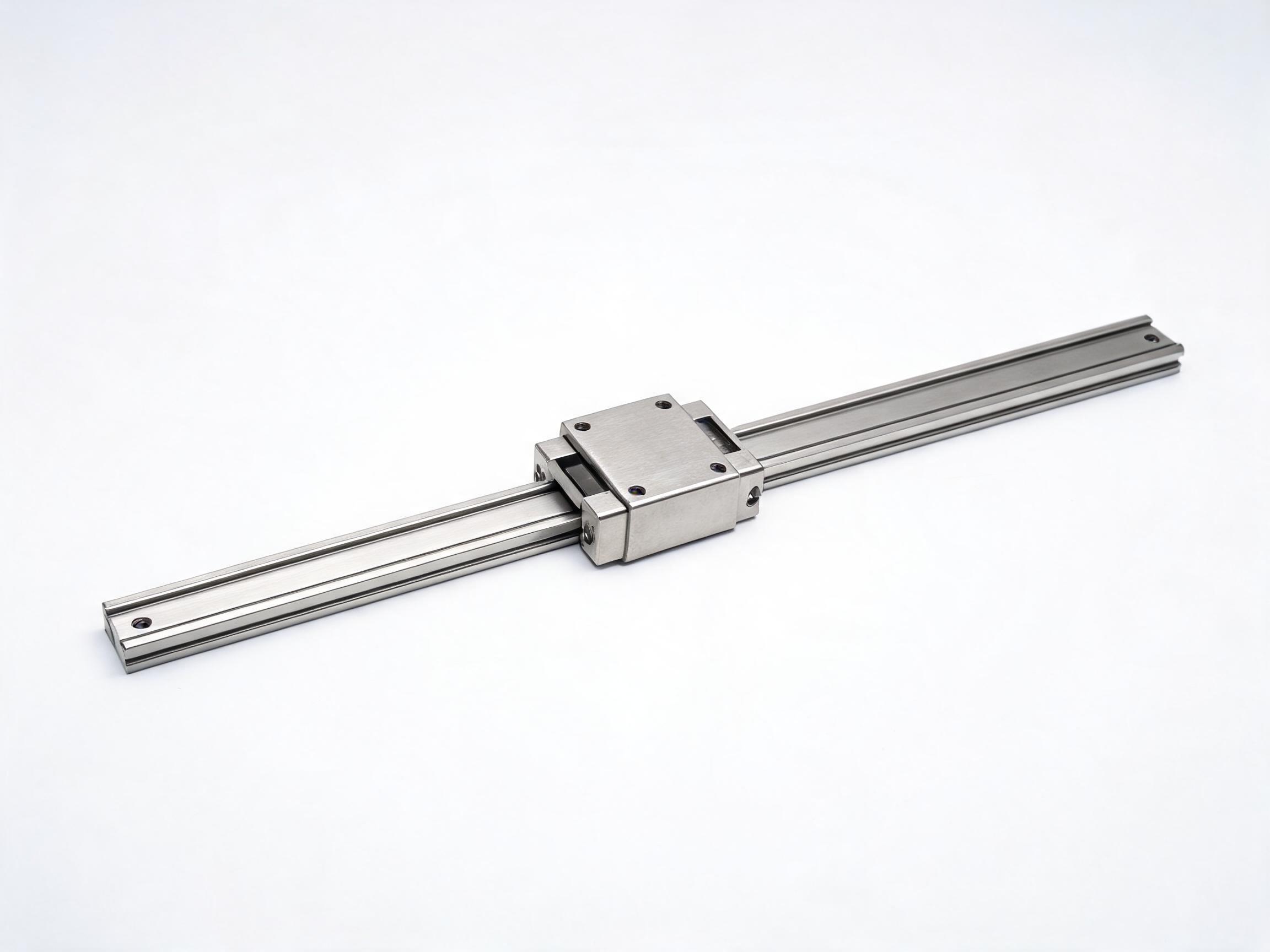
A buyer's guide to low profile linear rails for height-constrained designs: how total stack height is measured, where a lower profile costs load and stiffness, when a shaft-based slide unit is the lowest option, and how to compare three realistic choices without over-specifying the wrong axis.
In a tight height envelope, the number that decides the choice is not the rail height listed on the datasheet — it is rail plus carriage, measured at the mounting face. Here is how to read that number, where a lower profile costs load capacity, and when a shaft-based slide unit gets you lower than any profile rail can.
What this guide covers
- How to define total stack height so two options are compared on the same basis
- Three realistic low-profile options and what each trades away
- When a hardened-shaft slide unit is the lowest practical answer
- A worked comparison under one specified requirement, using listed catalogue figures
Start with stack height, not rail height
A profile rail datasheet will quote rail width and often rail height. Neither tells you how much vertical space the assembly actually consumes. The carriage sits on top of the rail, the load sits on the carriage, and the useful dimension is from the machine bed to the load mounting face. That is the total stack height, and it is the figure you must fix before comparing products.
Two failure modes show up when this is left vague. The first is sizing the rail alone and discovering the carriage pushes the load plate above a cover or through a guard. The second is the reverse: over-specifying a tall rail because the load rating looked comfortable, when a shorter stack would have passed with a smaller cross-section. Both are selection errors caused by comparing the wrong dimension.
Write the requirement down as a single measurement with the load attached. Then subtract the thickness of whatever sits between the carriage and the load — an adapter plate, a bracket, a sensor mount. What remains is the budget the rail or slide unit has to fit inside, including any clearance you need for the seals and for the screw or belt that drives the axis.
What a low profile rail actually gives up
Profile rails and shaft-based slides share one behaviour: reduce the section height and you reduce the section that carries load and resists moment. This is a trade-off, not a defect. A low-profile unit is doing the job you asked for — fitting a space a standard unit cannot — and the load figures quoted for it describe that smaller section honestly.
The trade-off shows up in three places:
- Dynamic and static load rating. A smaller ball or roller complement and a shorter effective raceway reduce the rating. Compare the figures at the same rail width, not across widths.
- Moment stiffness. Offset loads — a load whose centre of gravity sits away from the carriage centre — produce a moment the low-profile body resists with less leverage. If the load hangs off the side of the carriage, expect less resistance to tilt than a taller section of the same width would give.
- Sealing and contamination margin. A compact carriage has less internal space for lubricant retention and for seal geometry. End and side seals still protect the raceway, but the maintenance interval deserves a second look on dusty or high-cycle axes.
The correct response is to reduce the moment arm in the design — move the load centre over the carriage, or add a second rail — rather than to select a low-profile unit and hope the moment is tolerable. A pair of short low-profile rails on a wide base often carries an offset load better than one tall rail of the same overall length.
Three options, ranked by achievable height
In practice, height-constrained axes on small machine beds usually land on one of three families. The table below sets out what each family offers and where it stops being the right answer. Figures are the products' listed catalogue values.
| Family | Height situation | Listed load ratings | Where it is the right choice |
|---|---|---|---|
| Low-profile profile rail — EGH miniature series | Rail widths 9–15 mm; carriage height as low as 6 mm — the lowest carriage height of the three, but total stack height still depends on the rail body and mounting. | EGH15CA: 5.5 kN dynamic, 9.2 kN static. P5 ground raceway, Ra ≤0.4 µm. | You need a rigid, precisely guided axis in a shallow space, and the load is moderate. |
| Profile rail — MGN12 | Compact miniature profile rail; stack height depends on carriage type selected. No verified stack-height figure is quoted here — confirm it with the supplier before ranking MGN12 on height. | MGN12C: 3.7 kN dynamic, 5.4 kN static. 9Cr18Mo stainless standard. | Smaller cross-section is the priority, or a stainless rail is wanted for a wet or wash-down-adjacent axis. |
| Shaft-based slide unit — SBS16 | 18 mm total system height; listed as about 40% lower than the SBR16 reference, which is listed at 30 mm. Lowest of the three. | 5.2 kN dynamic, 8.0 kN static. 16 mm hardened shaft on aluminium support. | The envelope cannot take a rail-plus-carriage stack at all, or you want a ready shaft, support and carriage assembly. |
Ratings as listed by the manufacturer. Load ratings describe the bearing element, not the stiffness of the whole axis or the frame it is bolted to.
Reading the ratios instead of the headline numbers
The three families overlap more than the raw numbers suggest. Taking dynamic rating against static rating as a rough indication of how much reserve each unit keeps for shock and static parking loads, the EGH15CA (5.5 kN / 9.2 kN) and the SBS16 (5.2 kN / 8.0 kN) sit close together on both counts. The MGN12C is lower on both (3.7 kN / 5.4 kN), which is expected for a smaller miniature section.
That means the deciding question is usually not which unit has the highest rating — the two larger options are close — but whether the height difference between them changes your design. SBS16 states a total system height of 18 mm, roughly 40% below the SBR16 reference line, which the manufacturer lists at 30 mm, while the EGH family reaches a carriage height as low as 6 mm. Because the EGH figure is carriage height and the SBS16 figure is total system height, the two are not directly comparable. Put both into your stack measurement before deciding; a 6 mm carriage plus rail plus load plate may or may not come in under 18 mm, and only your actual assembly geometry settles it.
When a shaft-based unit is the lowest practical answer
A shaft slide unit is not simply a worse rail. It is a different architecture: a hardened shaft carried on an aluminium support, with a carriage riding the shaft. SBS16 makes this explicit — an 18 mm total system height, a 16 mm hardened shaft, and standard lengths from 150 to 500 mm on a 25 mm mounting pitch.
Three situations favour it. First, when the envelope is below what a rail-plus-carriage stack can deliver once the load plate and drive are added. Second, when you would otherwise have to design and align a shaft support yourself: the supported shaft, carriage and mounting pitch arrive as one assembly. Third, when the 25 mm mounting pitch matches an existing hole pattern on the machine bed, which simplifies the retrofit.
Two costs come with it. The shaft support occupies width, so check the lateral envelope as well as the height. And the 5.2 kN dynamic rating, while close to the EGH15CA's 5.5 kN, is achieved by a 16 mm shaft and its support — the stiffness of that support under an offset load is a separate question from the bearing rating, and worth raising with the supplier if the load centre sits off the carriage centre.
EGH: what the finish buys you in a shallow space
When the rail is going to be buried inside a compact assembly, service access is limited, so surface quality and sealing matter more than they would on an open frame. The EGH series lists a P5 ground raceway with Ra ≤0.4 µm and both end and side seals. A ground, low-roughness raceway supports smooth motion at low feed rates, which is often what a height-constrained axis is doing — a short stroke, a small sensor head, a fine adjustment stage. The end and side seals close the two directions contamination normally enters a compact carriage.
The EGH rail widths run from 9 to 15 mm, and the EGH15CA rating (5.5 kN dynamic / 9.2 kN static) applies to that width. If your load is well below this and the moment arm is small, the smaller widths within the same family are the place to look — they will bring the section down further, though the rating figures above are for the 15CA and do not transfer to narrower sizes.
A worked comparison under one requirement
Suppose a design fixes the following: a 6 kg load on a vertical axis, stroke 300 mm, load centre over the carriage centre, and a usable height of 22 mm from bed to load plate, with 4 mm of that taken by the adapter plate. That leaves 18 mm for rail plus carriage. This is a hypothetical requirement, used here only to show how the three options are judged against a stated number.
- SBS16 states an 18 mm total system height, which meets the 18 mm budget exactly. Lengths cover 300 mm within the 150–500 mm standard range. Listed ratings 5.2 kN dynamic / 8.0 kN static are far above a 6 kg load, so the binding constraint is height and alignment, not capacity.
- EGH with a carriage height as low as 6 mm leaves 12 mm for the rail body and any clearance. Whether that fits depends on the rail profile chosen and the mounting method; the carriage height alone is not the stack height. The EGH15CA rating of 5.5 kN dynamic is also well above the load.
- MGN12C at 3.7 kN dynamic / 5.4 kN static is likewise far above a 6 kg load and offers a smaller cross-section, but the stack height depends on the carriage type selected, which this article does not fix. No verified MGN12 stack-height figure is quoted here; confirm it with the supplier before including MGN12 in the height ranking.
Under this requirement the height figure, not the load rating, eliminates options. That is the normal outcome in a tight envelope: once the stack fits, capacity is rarely the limiting factor, and the real questions become moment stiffness, sealing and how the axis is driven.
How to specify it so the quote comes back right
Three numbers and one description get you a comparable answer:
- Total stack height available, from mounting face to load plate, with any adapter plate already subtracted.
- Load mass and where its centre sits relative to the carriage centre — directly over it, or offset, and by how much.
- Stroke length and the mounting hole pattern already fixed on the bed.
Then state the drive: screw, belt or manual, and whether the motor sits inside the same height envelope. A low-profile rail with a motor and coupling stacked above it can consume more height than a taller rail driven from the side. This is a common way a compliant stack becomes non-compliant at assembly.
Compare the three families directly
Listed dimensions and load ratings for the options discussed here: EGH miniature linear guideway rail and carriage, MGN12 linear rail, and SBS16 single-axis slide unit with low-profile carriage. Send your stack height, load position and stroke and the fit can be checked against the actual rail and carriage combination rather than the headline height.
FAQ
Is carriage height the same as total stack height?
No. Carriage height is one component of the stack. Total stack height runs from the machine mounting face, through the rail and carriage, to the face the load sits on. Adding an adapter plate, a drive screw or a motor above the carriage increases it further.
Can I use a low-profile rail and keep a standard rail's load rating?
Within one family, a lower section carries a lower rating — that is the trade-off, not a defect. The practical route to keeping capacity while reducing height is to use two short rails or to reduce the moment arm, rather than to expect a smaller section to match a larger one.
When should I choose a shaft slide unit over a profile rail?
When the envelope cannot take a rail-plus-carriage stack, when you want the shaft, support and carriage supplied as one aligned assembly, or when the standard mounting pitch matches your existing bed pattern. Check the shaft support's width and its stiffness under offset load, not only the bearing rating.
The load is small but the moment is large. Does the height decision change?
The height decision does not change, but the stiffness decision does. A low-profile section resists an offset load with less leverage, so if the load centre sits away from the carriage centre, plan a second rail or move the load centre before relying on the height saving.