
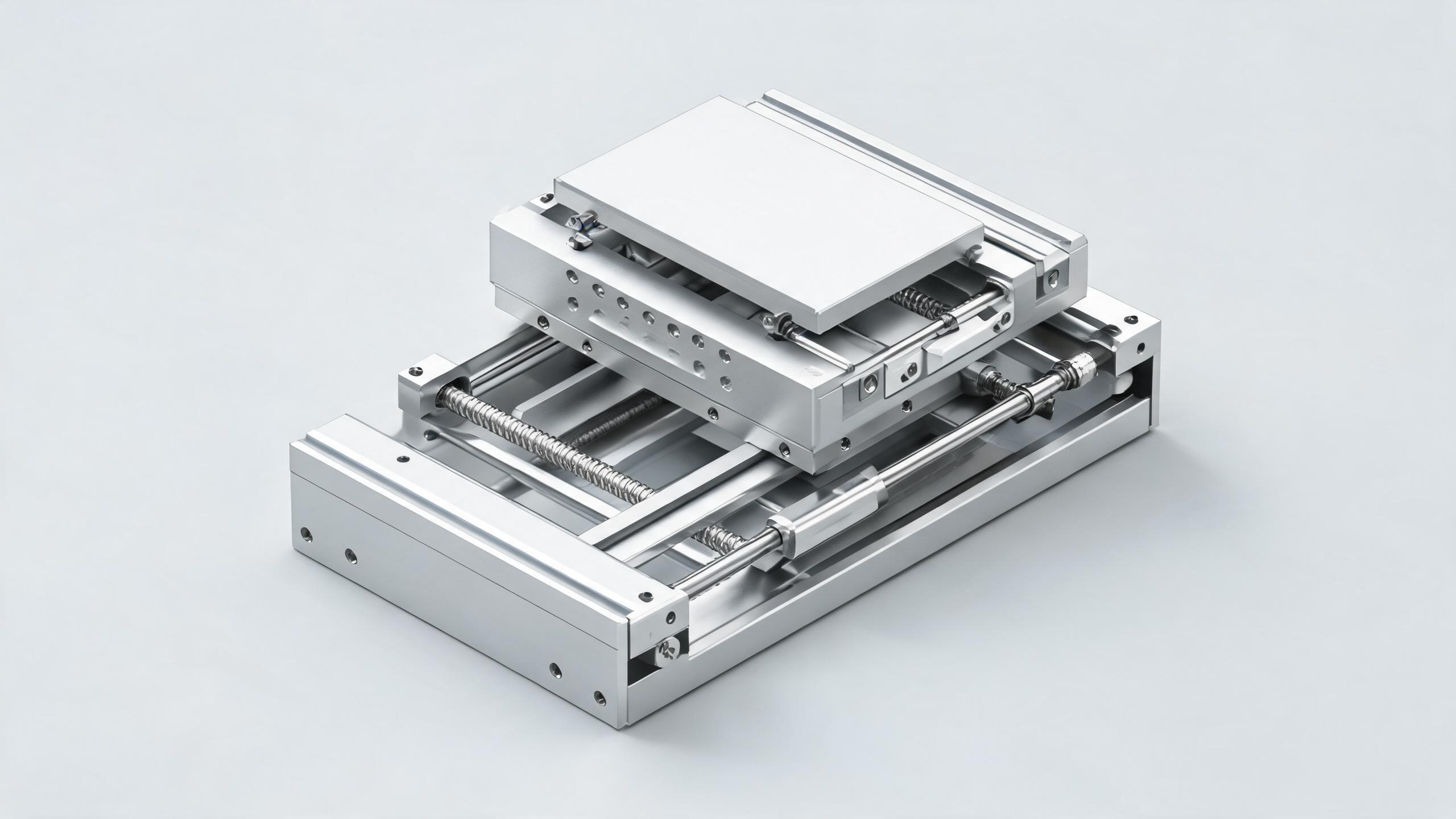
A technical guide for procurement engineers evaluating the TBR16 dual-axis synchronized linear motion system. Covers parallel rail configuration, torque resistance behavior, heavy load capacity, and how to specify linear guide bearing blocks and rail linear systems for gantry and pick-and-place applications.
MOTION CONTROL BUYER GUIDE
Why Dual-Axis Synchronization Matters for Gantry Builders
When you design a gantry, a dispensing robot, or an automated pick-and-place cell, the two rails must move as one. If the left carriage lags the right by even a fraction of a millimeter, the tooling twists, the workpiece marks, and the cycle time stretches while you troubleshoot. This is the problem the TBR16 dual-axis synchronized linear motion system is built to solve: two parallel rails, two carriages, one synchronized drive, and a structure that resists the torque that would otherwise bend the frame.
For buyers evaluating linear guide bearing block options and rail linear assemblies, the TBR16 is a specific configuration worth understanding before you compare quotes. This article covers the parallel rail layout, how the system handles torque, what heavy load capacity actually means in practice, and the specification questions you should ask any supplier.
- The TBR16 uses a parallel dual-rail configuration with synchronized carriages, designed for gantry-style loads where off-center force is the norm.
- Torque resistance comes from the rail spacing and bearing block geometry — wider rail centers and taller blocks reduce moment deflection.
- Heavy load capacity depends on the bearing block's ball circuit design and the rail's mounting surface quality, not just the rail profile size.
- Always request load-life curves and preload specifications from your supplier before committing to a linear guide system.
Parallel Rail Configuration: What It Does and Why It Works
A single rail linear guide constrains motion along one axis, but it cannot resist rotation around that axis. When you mount a beam across two rails, you create a plane of constraint. The TBR16's parallel rail arrangement does exactly this: two rail linear tracks mounted on a common base, with two linear guide bearing block carriages riding each rail and tied together by a moving bridge or platform.
The key geometry is the distance between the two rails — the span. A wider span increases the system's resistance to moments about the travel axis. For a given applied force at the tooling point, a wider rail center distance reduces the force each bearing block must react. This is the same reason a forklift has wide-set wheels: stability comes from the footprint, not just the tire size.
In the TBR16, the dual-axis synchronization means both carriages are driven by a single motor through a rigid coupling — typically a lead screw or belt — so the left and right sides advance at the same rate. This eliminates the "racking" problem where one side lags, which is the most common failure mode in poorly designed dual-rail systems.
Torque Resistance: How the Bearing Block and Rail Spacing Work Together
Torque resistance in a linear guide system is measured by the moment load ratings: Mr (pitch moment), Mp (yaw moment), and My (roll moment). These are the three rotational forces that try to tilt, twist, or roll the carriage off the rail.
| Moment Type | Axis of Rotation | Typical Cause in Gantry Use |
|---|---|---|
| Pitch (Mr) | Across the rail width | Load applied forward of the carriage center |
| Yaw (Mp) | Around the vertical axis | Off-center pulling or pushing at the tooling point |
| Roll (My) | Along the rail length | Load applied to one side of the carriage |
The TBR16's torque resistance is a function of two things: the bearing block's internal geometry and the rail span. The linear guide bearing block in the TBR16 uses a recirculating ball design with multiple rows of balls in contact. The more contact points and the wider the ball spacing, the higher the moment capacity. A taller block also helps — it increases the lever arm that resists roll.
But the block alone is not enough. Two rails spaced 200 mm apart resist roll moments far better than two rails spaced 60 mm apart, even with identical blocks. When you specify a TBR16 system, the supplier should provide the recommended rail spacing for your expected load. If they only give you a single "load capacity" number without reference to rail spacing, ask for the moment ratings and the calculation basis.
Heavy Load Capacity: Reading the Numbers Correctly
"Heavy load" is a relative term. For a small pick-and-place robot, 50 kg might be heavy. For a machining center, 500 kg is routine. The TBR16 is a 16 mm rail series — the "16" refers to the rail width. This places it in the medium-duty class, suitable for loads that a 12 mm or 9 mm rail cannot carry, but not for the extreme loads handled by 25 mm or 30 mm rails.
What matters more than the rail size is the dynamic load rating (C) and static load rating (C0) of the bearing block. These are the numbers that tell you how much load the block can carry for a rated life (typically 50 km of travel) and how much it can withstand without permanent deformation.
| Parameter | What It Tells You | Why It Matters |
|---|---|---|
| Dynamic load rating (C) | Load for 50 km rated life | Use this for life calculation under moving loads |
| Static load rating (C0) | Max load without permanent indentation | Use this for shock loads and stationary periods |
| Moment ratings (Mr, Mp, My) | Max rotational load before permanent deformation | Critical for off-center tooling and gantry spans |
| Preload class | Internal clearance or interference between balls and raceways | Higher preload = more rigidity, less backlash, more friction |
For a dual-axis system, the total load capacity is not simply double the single-carriage rating. The synchronization mechanism — the coupling between the two carriages — introduces additional forces. If the two sides are not perfectly aligned, one carriage carries more than its share. This is why the TBR16's rigid coupling design matters: it forces both sides to move together, distributing the load more evenly than a system with independent drives that may drift out of phase.
Application Scenarios: Where the TBR16 Fits
The TBR16 dual-axis synchronized system is commonly specified for:
- Dispensing and gluing machines — where the tool head must maintain a consistent height and angle across the full work area, and off-center forces from the dispensing nozzle create roll moments.
- Light assembly gantries — pick-and-place units moving components between stations, where the load is offset from the carriage center.
- Inspection and measurement systems — where a camera or sensor traverses a flat panel, and any tilt would distort the reading.
- 3D printers and laser engravers — where the gantry bridge spans a fixed bed and must resist the moment created by the tool head's weight and acceleration.
In each case, the buyer's real question is not "can it carry the load?" but "can it carry the load without deflection that affects the process?" The TBR16's parallel rail configuration and synchronized drive address this directly.
Specification Checklist for Buyers
When you request a quote for a TBR16 system or any comparable linear guide bearing block and rail linear assembly, ask the supplier for these specific data points:
- Dynamic and static load ratings for the bearing block, in Newtons.
- Moment ratings (Mr, Mp, My) in N·m, not just a single "max load" figure.
- Rail straightness tolerance — typically expressed in µm per meter. This directly affects system accuracy.
- Preload class and whether the system is available with light, medium, or heavy preload.
- Recommended rail span for your expected load and tooling offset.
- Life calculation — request the L10 life formula and the expected travel life at your operating load.
- Mounting surface requirements — the flatness and parallelism of the base plate that the rails mount to. Many "system failures" are actually mounting surface failures.
A linear guide system is only as good as its mounting surface. A rail mounted on a warped plate will bind, wear unevenly, and fail early — regardless of the bearing block's rated capacity.
Common Specification Mistakes
Mistake 1: Choosing rail size by load alone. The TBR16's 16 mm rail width is not the only factor. Two systems with the same rail size can have very different load capacities if the bearing blocks have different ball circuits. Compare the bearing block ratings, not just the rail profile.
Mistake 2: Ignoring preload. A system with zero preload may feel smooth but will have backlash when the direction reverses. For positioning applications, medium preload is usually the right choice. For heavy shock loads, high preload adds rigidity but increases friction and heat.
Mistake 3: Forgetting the synchronization mechanism. A dual-axis system is only synchronized if the drive coupling is rigid. If the supplier offers a belt drive with significant elasticity, the two sides may drift under load. Confirm the coupling type and its torsional stiffness.
FAQ
Q: What is the difference between a single rail and a parallel dual-rail system?
A: A single rail constrains motion along one axis but allows rotation around it. A parallel dual-rail system constrains both translation and rotation, providing higher rigidity and torque resistance. The TBR16 uses the dual-rail configuration for applications where off-center loads are expected.
Q: How do I know if the TBR16 is the right size for my application?
A: Calculate your applied loads — including moments from off-center tooling — and compare them against the bearing block's rated moment capacities. If your moments exceed the ratings, you need a larger rail series or a wider rail span. Your supplier should provide the calculation method or perform it for you.
Q: Can I replace an existing linear guide with the TBR16 without redesigning my machine?
A: Only if the mounting dimensions match. The TBR16 has specific rail width, height, and mounting hole patterns. If your current system uses a different rail profile, you will need to re-machine the mounting surface. Always verify the dimensional drawings before ordering.
Q: What maintenance does a linear guide bearing block require?
A: Regular lubrication is the primary requirement. The TBR16 bearing blocks have grease fittings for this purpose. The lubrication interval depends on speed, load, and environment. In clean, moderate-speed applications, monthly lubrication is typical. In dusty or high-speed environments, weekly may be necessary.
Making the Final Decision
The TBR16 dual-axis synchronized linear motion system is a practical choice for medium-duty gantry applications where parallel rail configuration, torque resistance, and predictable load capacity are the deciding factors. The system's value is not in any single component — it is in how the linear guide bearing block, rail linear tracks, and synchronized drive work together as one assembly.
When you compare quotes from different suppliers, ask each one for the same specification sheet: load ratings, moment ratings, preload options, and rail straightness tolerance. A supplier who can provide these numbers confidently is a supplier who understands the application. A supplier who only says "it can handle your load" without data is asking you to take a risk with your production line.
If you are currently evaluating a TBR16 system for a specific application, we recommend sending your load conditions — including the tooling weight, the offset distance from the carriage center, and the expected cycle rate — to your supplier for a formal life calculation. This is a standard engineering service and should be provided free of charge as part of the quotation process.
For more information on linear guide systems and motion control components, please contact our engineering team with your application details. We can help you select the correct rail size, preload class, and rail span for your specific requirements.