
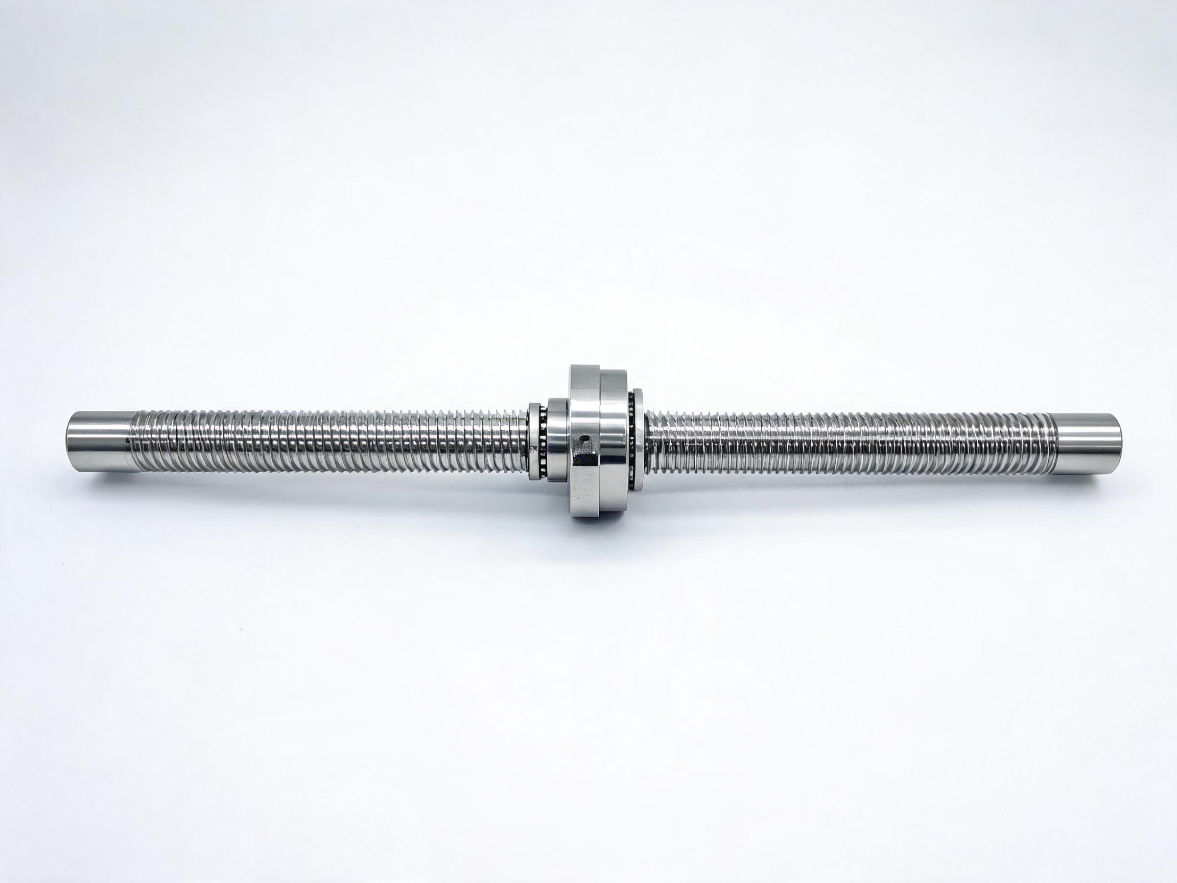
Repeatability is a property of the whole axis. The guide contributes rigidity and preload, the ball screw's precision class sets positioning granularity, and assembly errors between rails appear as lost motion. This explainer separates those contributions and walks through the XY200 cross-slide table, which holds ±0.01 mm per axis with HGR15 rails, SFU1605 C7 screws and a verified perpendicularity of 90°±0.02°.
Linear Guide Rail Repeatability: What Sets It in an Axis
Buyers sizing a linear axis often ask for a repeatability number and expect the answer to come from the guide rail catalog. It does not. The rail and carriage fix how rigidly the load is carried and how much clearance has to be absorbed before motion is transmitted, but the axis repeats only as well as the combination of guide, screw and assembly allows. On a loose or misaligned frame, even a precision-class screw will produce lost motion that dwarfs its stated accuracy.
Key takeaways
- Repeatability is an axis property; the guide is one contributor, not the source.
- The guide acts through rigidity and preload; lash in the carriage turns into lost motion.
- The ball screw's precision class sets positioning granularity, not the axis's final repeatability.
- Assembly errors — above all alignment between rails — appear directly as lost motion.
- The XY200 worked example reaches ±0.01 mm per axis only as a complete system.
Why the guide alone cannot promise repeatability
A recirculating linear guide is a loaded rolling interface. When the carriage moves, rolling elements enter and leave the load zone, and the carriage sits inside whatever internal clearance the preload has removed. A guide sold as preloaded presents a stiffer, more tightly controlled interface; its catalog will state a repeatability figure under defined conditions. What the catalog cannot state is whether that figure survives in the finished machine.
In an axis, the guide's contribution is structural. A rigid, preloaded guide resists deflection under the cutting or positioning loads so that the screw's command actually moves the load. If the guide is undersized or the preload is wrong for the load direction, the carriage deflects before the encoder or motor sees motion, and the axis returns to a different point than it left. That error is not in the rail; it is in the stiffness budget of the axis.
The screw's contribution is different. Its precision class describes how closely the actual travel matches the commanded travel over a defined length, and its nut design describes how much axial clearance can move before the screw drives the load. If the nut clearance is large, the screw can rotate without moving the carriage until the clearance is consumed — a source of lost motion no guide preload can correct.
The three contributions, separated
| Element | What it controls | How it fails the axis |
|---|---|---|
| Guide rail and carriage | Rigidity, preload, straight-line support of the load | Deflection under load, clearance in the rolling interface, misalignment between rails |
| Ball screw and nut | Positioning accuracy class and axial clearance | Nut lash and class-related travel error translate into command-following error |
| Assembly | Parallelism and perpendicularity between rails, base flatness, mounting fit | Rail misalignment and base distortion appear as lost motion and drift |
Guide rigidity and preload
The guide establishes the stiffness of the moving interface. Preload reduces internal clearance; a stiffer rail sets a smaller deflection per unit load. Because repeatability is about returning to the same point under the same load, the guide matters most when the load direction or magnitude varies during the cycle. For a constant, light load, an entry-level preload can hold position; for varying or offset loads, the axis needs the stiffness to match.
Screw precision class and axial clearance
The screw sets positioning granularity. In our product records, rolled screws and ground screws sit in different classes. The rolled SFU Series Rolled Ball Screw Assembly is a C7 product with positioning accuracy of ±0.05 mm per 300 mm and a single-nut design. The ground SFE Series Ground Ball Screw Assembly is a C5 product at ±0.008 mm per 300 mm, with a double-nut design and axial clearance under 0.005 mm. A double-nut zero-backlash option, the DFU series, holds axial clearance under 0.003 mm.
Those numbers describe travel accuracy and nut clearance. They do not by themselves give the axis a repeatability figure; a C5 screw on loose rails still produces lost motion from the guide side. The screw class matters most when the requirement is command-following accuracy over distance, and the nut clearance matters when reversing direction.
Assembly error and lost motion
Assembly is where separate components become one axis. If the two rails of a stage are not parallel, the carriage has to skew as it travels; that skew shows up as variation at the point of return. If the base is not flat, bolting the rails down distorts them, and the preload changes along the length. These errors are mechanical and show up as lost motion: the axis moves a little before the load follows, and the reversal point shifts.
In short: the guide does not set repeatability by itself, but the assembled axis does. Buying a high-class screw and a good rail still leaves the assembly to define the result.
A worked example: the XY200 cross-slide table
The XY200 Precision Cross Slide Table shows the three contributions working together. It is a dual-axis stage with HGR15 rails and HGH15CA carriages, driven by dual SFU1605 C7 ball screws with a 5 mm lead. Its envelope is 340×340×60 mm. The datasheet lists repeatability at ±0.01 mm per axis.
The assembly specs around that figure are the informative part. Perpendicularity between axes is 90°±0.02°, verified by CMM, and the base plate flatness is held within 0.01 mm over 300×300 mm. Those values constrain the assembly contribution. The 0.01 mm flatness limits distortion transferred into the rails; the perpendicularity tolerance limits the squareness error between the two axes. The C7 screw class and single-nut design set the travel and clearance behavior; the HGR15 rail with HGH15CA carriage provides the rigidity and preload.
Worth noting is what this example implies about the specification process. A buyer asking for ±0.01 mm per axis is asking for a system figure, not a screw class. The C7 screw's own travel accuracy is ±0.05 mm per 300 mm, so the axis repeatability of ±0.01 mm depends on the assembly, the preload and the measurement conditions together. If those conditions change — for example, a heavier or offset load — the axis result needs to be re-established rather than assumed from the table.
How to specify an axis requirement
When a repeatability target matters, the requirement should be written at the axis level, with the elements that produce it named. Three pieces of information make the requirement usable:
- The repeatability and the direction it applies to. Position repeatability under a defined load is a different requirement from reversal repeatability, and a specification should say which one is being quoted.
- Load and stroke. The guide's stiffness contribution depends on the load, and the screw's travel error accumulates over length. A repeatability statement should be tied to the same load and stroke as the application.
- Assembly tolerance. Flatness and perpendicularity tolerances belong in the requirement, not only in the drawing. If the base can distort during mounting, the repeatability achieved at assembly may not hold after installation.
For a screw-dominated requirement, the relevant class and nut clearance are available; for a guide-dominated one, the rail size and carriage preload. If the axis combines both, the requirement should be quoted as a system result, and any unverified element left as "confirm per datasheet."
FAQ
Does a higher ball screw class raise the axis repeatability?
Not by itself. A C5 ground screw cuts travel error to ±0.008 mm per 300 mm and a double-nut design holds axial clearance under 0.005 mm, but if the rails or the assembly are loose, the axis can still lose motion at reversal. The screw class sets positioning granularity; the assembled axis sets the result.
What causes lost motion in a linear guide axis?
Lost motion comes from the parts of the system that must move before the load follows. In the guide, that is clearance and deflection; in the screw, nut axial clearance; in assembly, rail misalignment and base distortion. The fix is to locate which contribution dominates — measuring reversal error with the screw isolated from the guide is one way — before changing parts.
Can the XY200's ±0.01 mm per axis be applied to any axis I build?
No. It is the repeatability the datasheet lists for that complete assembly with HGR15 rails, HGH15CA carriages, dual SFU1605 C7 screws and a 5 mm lead, built to a base flatness of 0.01 mm over 300×300 mm and perpendicularity of 90°±0.02°. A different rail size, screw lead, load or assembly tolerance changes the axis result; confirm per datasheet for the configuration in question.