
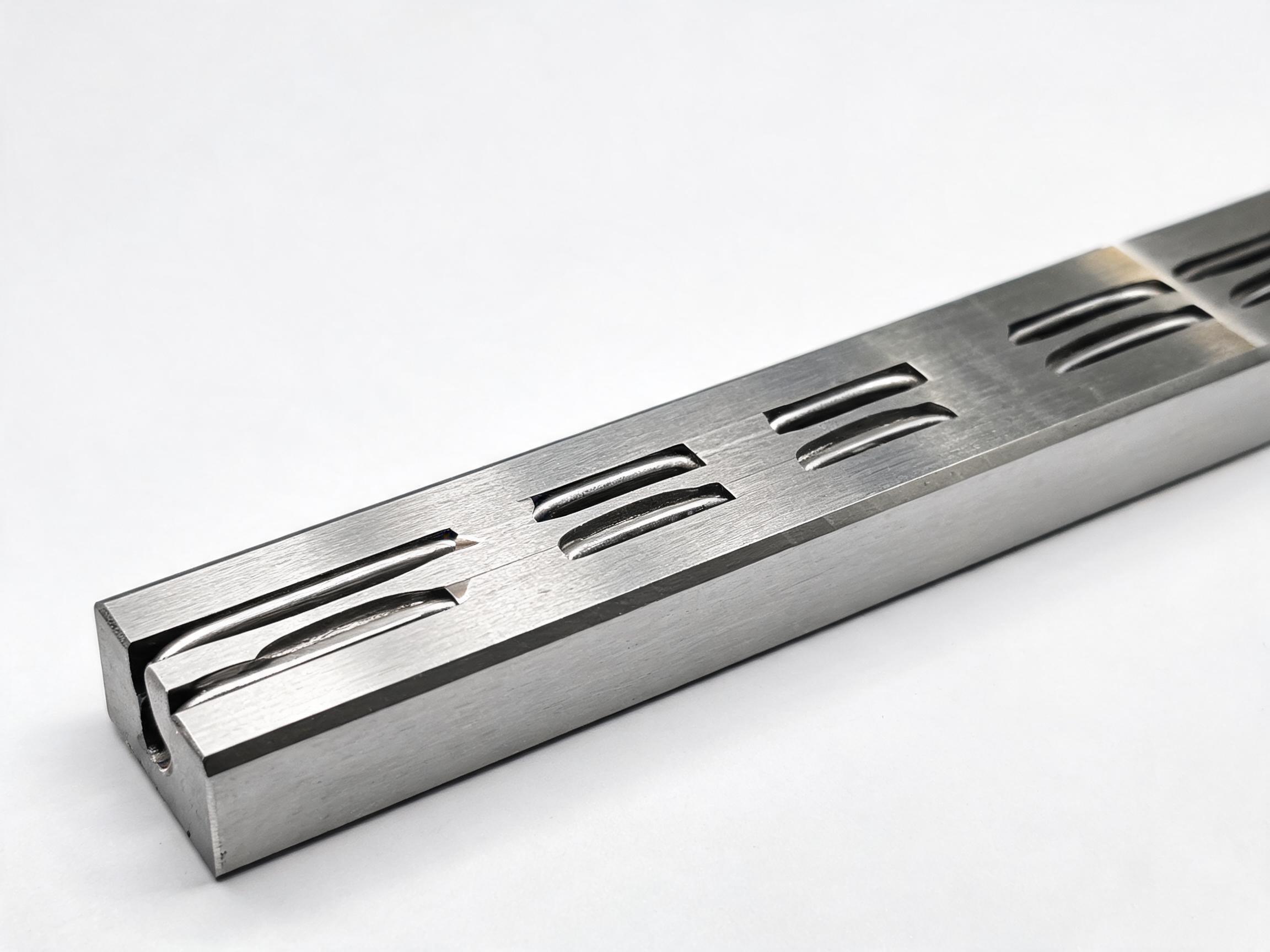
Shock loading, or impact load, is the short-duration force an axis feels when it accelerates or stops faster than its drive and structure can absorb. This article explains what that does to raceways and ball circuits on a linear guide, why static load rating and preload margin matter more than the dynamic rating under impact, and how to respond at selection stage with rail size, carriage geometry and preload grade — and when to stop calculating and hand the real motion profile to the supplier.
Shock loading is the force a mechanism feels when it is asked to change speed faster than its drive and structure can absorb. On a linear guide, that shows up in the raceways and ball circuits before it shows up anywhere else.
A braked stop, a pick-and-place head that slaps down onto a part, a pressing stroke that bottoms out — these are the conditions buyers usually have in mind when they ask what impact load means for a linear guide. The sizes and part numbers may look fine on a standard calculation. The question is whether the calculation covered the moment the axis stops.
What Shock Loading and Impact Load Mean in Linear Motion
Shock loading, also called impact load, is a short-duration force produced by a sudden acceleration or a sudden stop. In a linear axis, the carriage has mass, the payload has mass, and the drive is trying to change their velocity. When velocity changes quickly, the force needed to do it is concentrated into a brief interval rather than spread over a smooth cycle.
Two things make this different from ordinary running load:
- Duration is short. The peak appears and disappears within a fraction of the motion cycle, so a time-averaged or duty-cycle figure does not describe it.
- Direction is not always radial. A hard stop can push the carriage along the rail, lift it off the rail on an inverted axis, or twist it about the rail.
This is why a rail that runs comfortably under normal travel can still be the wrong rail for an axis that brakes hard or presses. The duty point and the impact point are two different load cases.
- Shock loading is a transient force from fast acceleration or stop, not a steady running load.
- Under impact, the static load rating and the preload margin describe the guide better than the dynamic rating alone.
- Repeated impacts damage raceways and ball circuits through surface indentation, which can show up as preload loss before any visible failure.
- Selection responses are rail size, carriage geometry, preload grade, and a real motion profile for the supplier.
Why Static Rating and Preload Margin Matter More Than Dynamic Rating
Dynamic load rating describes a guide under rolling motion and is the usual number buyers compare when sizing for travel life. It is not the number that governs a hard stop.
Under impact, the relevant questions are: what peak load can the rolling elements and raceways take without permanent deformation, and how much preload reserve does the carriage have before that peak removes it. That is the territory of static load rating and preload grade.
Take a common comparison from our HGR Series heavy-duty guideway rail and HGW Series wide-body carriage range:
| Item | Dynamic load rating | Static load rating |
|---|---|---|
| HGR20 rail | 16.7 kN | 26.7 kN |
| HGW25CA carriage block | 28.4 kN | 42.1 kN |
The static figure is the one that sits closer to an impact condition: it is the load case where the guide is not rolling away from the force. When an axis brakes hard or presses, the moment of impact is exactly that — the carriage is momentarily stationary against a force it did not generate by rolling.
Preload works alongside it. A carriage that is preloaded has rolling elements already in contact under a controlled preload. In plain terms, preload removes internal clearance so the carriage does not shift within its own running fit when the load direction reverses. Under impact, that reserve is what keeps the carriage from moving before the balls take load. Once the impact peak uses up the margin, the carriage runs with less preload than it was set to, and the axis feels looser even though nothing looks broken.
A note on method: the figures above are catalogue ratings for the named models. Whether they are sufficient for a specific braked stop or pressing stroke depends on the actual motion profile of that machine, which is why the profile matters more than the catalogue comparison.
What Repeated Impacts Do to Raceways and Ball Circuits
A single overload event is a design concern. Repeated mild impacts are a wear concern, and they tend to progress in a specific way.
Surface indentation at ball contact points
When impact force at a ball-to-raceway contact exceeds what the surface can carry elastically, the contact area is permanently deformed. The result is a small indentation at each ball position under the peak. On a rail that experiences the same stop position every cycle — a fixed pressing depth, a hard end stop — those indentations can concentrate at the same locations rather than distributing along the raceway.
Damage that behaves like false brinelling
Where an axis sits under a small oscillating or repeated contact load without much travel, the ball and raceway contact can develop marks that resemble false brinelling. The practical symptom is the same: the raceway surface is no longer uniform, and the guide no longer runs with the smoothness it had when new.
Preload loss
This is often the first thing a user notices. The indentation slightly changes the contact geometry and clearances inside the block, and the carriage runs with reduced effective preload. On a machine where positioning matters, that shows as changing deflection under load, more noise in the axis, or an operator complaint that the head “feels loose” even though it is still moving.
These are possible mechanisms under impact conditions, not a diagnosis of any particular machine. Confirming which one is present on a given axis requires the actual motion profile, installation condition and maintenance record, and in most cases a look at the raceway by the guide supplier.
It is also worth separating impact from ordinary fatigue. Fatigue life under normal rolling is a long-term accumulation. Indentation from impact happens at the moment of the peak, and it can appear early in the life of an otherwise correctly loaded guide.
What to Do at Selection Stage
If the axis has a hard stop, a slap-down or a pressing operation, it should be treated as an impact case at the selection stage rather than corrected later in the field.
Size up the rail rather than only the carriage
Rail size determines the raceway geometry and the ball size available to carry load. Going up a size increases both dynamic and static capacity and gives more room before an impact peak reaches the point of permanent deformation. The HGR Series heavy-duty guideway rail is available in sizes 15 to 45 with lengths to 4000 mm, so a step up in size usually stays within the same mounting concept.
The rail itself is made from 55# high-carbon steel with an induction-hardened raceway at 58–62 HRC. Hardness at the raceway is directly relevant to impact, because permanent deformation is a surface event: the harder the contact surface, the higher the load it can carry before indenting.
Consider a wide-body carriage where the impact has a moment
Impact is rarely a pure radial push. A braked stop at the end of a cantilevered payload produces pitch and yaw moment; an inverted axis can push the carriage away from the rail. A carriage with a wider mounting footprint spreads the load across the ball rows and resists that moment more effectively than a narrow one.
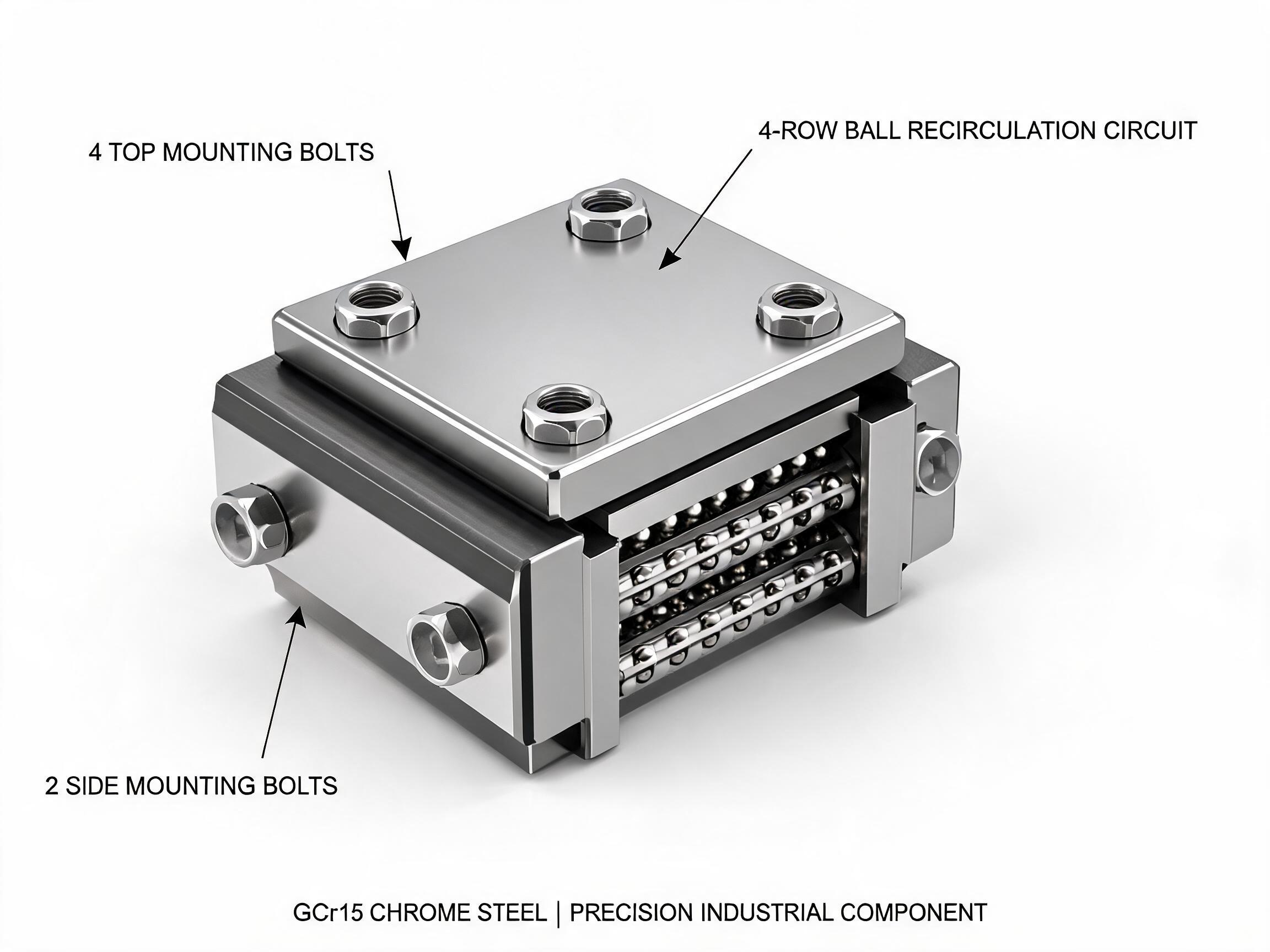
The HGW Series wide-body linear guideway carriage block has a mounting footprint 20–30% wider than the HGH flange type, which is the geometry that resists pitch and yaw moment and lift-off on inverted axes. Its base ball geometry — a four-row arrangement — carries radial, reverse-radial and lateral loads simultaneously, which matters when the impact direction is not known precisely at the design stage.
Self-aligning tolerance for this carriage is ±0.5°, which is relevant on machines where the two rails of an axis are not perfectly parallel and an impact load would otherwise be concentrated on one carriage.
Choose preload grade deliberately, not by default
Preload grade is not only about positioning accuracy. It also sets how much clearance has been removed from the running fit, and therefore how much of an impact peak the carriage can absorb before it moves. Available preload grades for the HGW Series are C0, C1 and C2. A higher preload grade reduces internal clearance and gives more reserve against a reversing or lifting impact, at the cost of higher running friction. The selection should follow the impact direction and the positioning requirement of the axis, not just the accuracy class of the machine.
When to Stop Calculating and Talk to the Supplier
Catalogue ratings describe a model under defined conditions. They do not describe a specific braked stop with a known deceleration time, a specific pressing depth with a specific material, or a specific pick-and-place head with an offset centre of gravity. Past a certain point, further arithmetic on the catalogue figures adds less certainty than a correct description of the motion.
What the guide supplier needs in order to give a useful answer is the real motion profile, not a summary:
- The moving mass and, if relevant, the payload mass.
- Cycle time and the travel of the axis.
- How the axis decelerates — brake, hard stop, servo ramp — and over what time or distance.
- The orientation of the axis: horizontal, vertical or inverted.
- Whether the impact recurs at the same position every cycle.
- The mounting arrangement: number of rails, number of carriages, and whether the load is centred or offset.
With that profile, questions such as whether HGR20 or a larger size is appropriate, whether a standard flange carriage or an HGW wide-body carriage should be used for a given moment, and whether C0, C1 or C2 preload matches the application can be answered against the actual conditions instead of assumed ones.
For specifications and dimensional data on the guideway rail, see HGR Series heavy-duty linear guideway rail. For the wide-body carriage range described above, see HGW Series wide-body linear guideway carriage block.
FAQ
Is shock loading the same as impact load?
The two terms are used interchangeably in linear motion. Both describe a short-duration force from a rapid change in velocity, as opposed to the steady running load a guide sees during normal travel.
Can I just apply a safety factor to the dynamic load rating?
A safety factor on the dynamic rating does not describe the impact case, because the dynamic rating is a rolling-fatigue figure. Impact is a deformation and preload question, which is closer to the static rating and the preload grade.
How do I know if an axis actually has a shock loading problem?
Typical indications are changed deflection under load, increased running noise, or a carriage that feels less tight than when installed. Confirming the cause means reviewing the real motion profile, the installation condition and the maintenance record, and in most cases having the guide supplier inspect the raceway. None of these symptoms identifies a cause on its own.
Does a higher preload grade always solve impact problems?
No. A higher preload grade increases the reserve against impact by reducing internal clearance, but it also raises running friction. The correct grade depends on whether the axis needs the extra reserve against a reversing or lifting impact, and on the positioning and friction requirements of the machine.