
A practical guide to configuring ball screw end supports: how the fixed end and floating end share the load, when each arrangement is required, how to match BK/BF blocks to screw diameter, and which assembly mistakes cause binding, noise, and premature bearing failure.
The fixed end carries both radial and axial loads and locks the screw's axial position; the floating end carries radial load only and lets the screw elongate and contract as it warms and cools. Nearly every horizontal ball screw axis uses one of each. Assemblies that use two fixed ends, or two floating ends, run into binding, noise, or premature bearing failure because the screw is either over-constrained or free to drift out of position.
The short version: put the motor at the fixed end with a pair of angular contact bearings so the screw cannot move axially, and support the far end with a single deep-groove bearing that slides axially. Match the bearing blocks to the machined journal diameter of the screw, not to the nut or the motor frame.
What each end actually does
The fixed end
The fixed end is the reference for the whole axis. A paired angular contact bearing set is preloaded against itself, so the screw's axial position is held to a few micrometers of play while radial load is shared between the bearing pair. Because the screw is axially located here, the nut's commanded position maps directly to the load's real position. That rigidity is the reason the drive and the origin of your coordinate system sit at this end.
Floating pre-load on a paired set is not a cosmetic detail. Too little preload leaves axial clearance that shows up as lost motion when the load changes direction; too much preload raises running temperature and shortens bearing life. Follow the bearing manufacturer's preload specification for the set you buy, and confirm the required torque with the datasheet rather than guessing.
The floating end
The floating end carries radial load and nothing else. A single deep-groove bearing takes the side load of the screw's self-weight and any belt tension, while its outer housing slides axially in the support block. When the screw expands during a long run or warms up in a hot machine frame, the floating end absorbs that movement instead of pushing it back into the fixed bearings.
Thermal growth is the reason this end exists. For a screw running for hours in a warm enclosure, the axial expansion must go somewhere. If both ends are fixed, the fixed bearings absorb it as extra axial load, and the screw either stretches or the bearing seats wear. If both ends float, the screw is not located at all and the nut position drifts.
When each configuration is needed
Configuration follows from screw length, speed, required positioning rigidity, and whether the axis runs vertically. The table below summarizes the practical boundaries.
| Condition | Recommended support arrangement | Reason |
|---|---|---|
| Short horizontal axis, low speed | Fixed end plus simple radial support at the far end | Little thermal growth to absorb; radial support keeps the screw from whirling |
| Long horizontal screw, continuous duty | Fixed end plus floating end | Absorbs thermal elongation without loading the fixed bearings |
| High-speed axis | Fixed end with paired angular contact set; floating end to prevent whip | Axial rigidity at the drive end and radial guidance along the length |
| Vertical Z axis | Fixed end at the top, carrying the screw's weight and the axial load | Prevents the screw and load from settling under gravity; floating end below |
| High-precision positioning | Fixed-fixed with controlled preload, only where the design accounts for thermal growth | Maximum axial rigidity, but requires a thermal plan |
High-speed and vertical cases also depend on critical speed, buckling load, and nut lubrication. Confirm those limits with the datasheet for the specific screw and support set.
Horizontal axes that carry a heavy load or run against a significant axial force benefit from a larger screw and a correspondingly larger support. The SFU2510 Rolled Ball Screw Assembly with Flange Nut, for example, uses a 25 mm shaft with a 10 mm lead, delivers 17.2 kN dynamic and 26.5 kN static load, and is BK25/BF25 compatible — a natural step up from a 16 mm screw when axial load or screw length grows.
Matching BK and BF blocks to screw diameter
Support block series are sized to the screw's machined journal, so the block model must match the shaft diameter. BK blocks are the fixed end; BF blocks are the floating end. A 16 mm screw pairs with BK12 and BF12; a 25 mm screw pairs with BK25 and BF25.
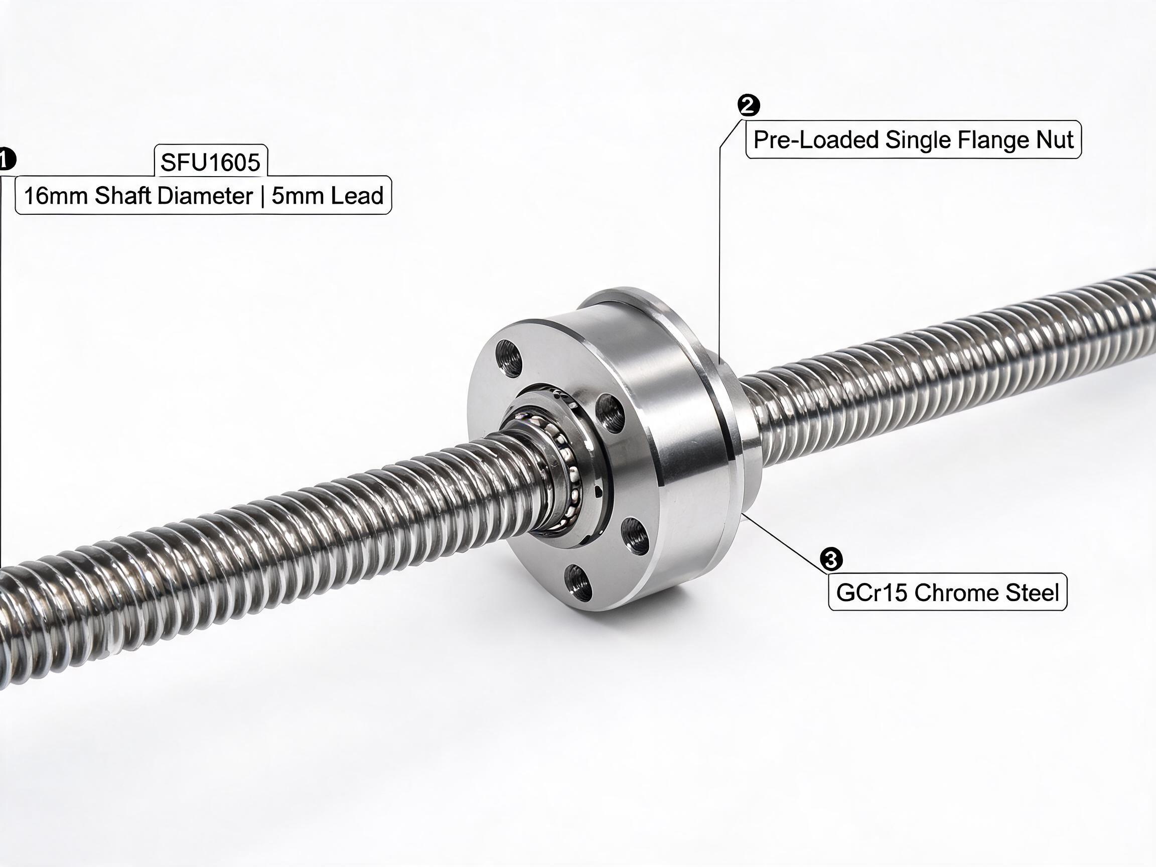
This is not a formality. A 16 mm rolled screw such as the SFU1605 ships with both ends machined for BK12/BF12 bearing blocks and fits standard 6204 support bearings without modification, so the end journals are already cut to the right diameter and bearing seat. If you substitute a differently sized block, the housing bore and the journal no longer agree, and the assembly either will not seat or will run with clearance. Order the blocks in the same series as the screw's machining.
Rigidity is a separate variable from size. Standard support blocks fit a standard bearing; higher-rigidity assemblies specify a different bearing set or a preloaded pair. On the SFE Series Ground Ball Screw Assembly, for example, the SFE2005 uses a 20 mm shaft and a pre-loaded double nut, is C5 precision grade, and achieves ±0.008 mm per 300 mm — roughly six times tighter than rolled C7 at ±0.05 mm per 300 mm. The bearing assembly has to be selected to match that precision requirement, not just the shaft diameter.
Common assembly mistakes
Over-constraining the floating end
If the floating end housing is clamped so tightly that the bearing cannot slide, it becomes a second fixed end in practice. The screw then has nowhere to expand. The result is a warm-running assembly, increased axial load on the fixed bearings, and a nut position that changes as the machine heats up. Leave the floating end free to slide, and check that nothing in the frame around it pinches the float.
Mixing support sizes
A BK12 fixed block and a BF25 floating block cannot share one screw. The journals differ, the bearing seats differ, and on a mismatched assembly the shaft floats freely in one housing. Order both blocks as one matching pair in the same series as the screw's end machining.
Ignoring unsupported length
Screw length between supports is defined by the blocks, and it determines critical speed and buckling. The SFU Series Rolled Ball Screw Assembly is rolled from GCr15 (52100) chrome steel, induction hardened to HRC 58-62, with C7 grade and ±0.05 mm per 300 mm lead accuracy. The SFU1605 (16 mm shaft, 5 mm lead) reaches 6.8 kN dynamic load with a single nut; those figures apply to the screw and nut, not to the maximum span you can run unsupported at any speed. Confirm critical speed and buckling limits with the datasheet for your span and speed.
Ignoring thermal growth
A screw that runs in a warm enclosure grows in length. Treat growth as a design input: give the floating end its range, and if the application cannot tolerate any axial movement at that end, plan for a temperature-compensated or fixed-fixed design rather than simply locking both ends and hoping.
Preloading the fixed pair by feel
Hand-tightening a paired angular contact set leaves either clearance or excessive preload. Both show up later as lost motion or heat. Use the bearing maker's specified preload and torque, and check the assembly by measuring axial play and running temperature after first start-up.
Decision checklist
- Is the screw horizontal or vertical? Vertical axes need a fixed end that carries the load.
- How long is the screw, and how much thermal growth does it see? Long, warm-running screws need a free floating end.
- What positioning rigidity does the application need? High precision may justify a ground screw (C5 or similar) with a matched, preloaded bearing set.
- What is the screw's machined journal diameter? Match BK and BF blocks to that diameter — 16 mm to BK12/BF12, 25 mm to BK25/BF25.
- Is the floating end actually free to slide in its housing after installation?
- Is the fixed end preloaded to the bearing maker's specification, with axial play measured at commissioning?
- Have critical speed and buckling for the actual unsupported span been checked against the datasheet?
- Are all parts from one matched screw-and-support series, so journals, housings, and bearings agree?
Get the fixed/floating arrangement right and the rest of the axis follows: the screw stays located, the bearings stay loaded as designed, and the nut position holds through warm-up. The two details that most often go wrong are matching the block series to the shaft diameter and keeping the floating end genuinely free.