
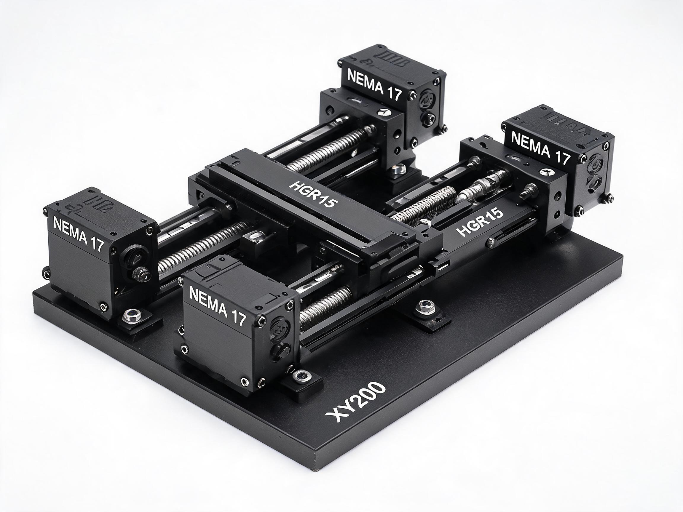
A machine builder's guide to choosing between an integrated precision cross slide and a self-built XY table, with ball screw and profile rail selection criteria, expected accuracy, and assembly order.
Build vs. Buy Guide
Two routes produce a working two-axis stage: buy an integrated precision cross slide table, or build your own XY table from ball screws and profile rail carriages. The integrated table is the faster path when its advertised perpendicularity and repeatability cover your application. The self-built path makes sense when travel, mounting pattern, drive placement, or budget must be controlled at the component level. The decision comes down to how much alignment work you can absorb and how tightly you need to define the interface.
Key takeaways
- An integrated table such as the XY200 arrives with dual ball screws, stated 90° perpendicularity within ±0.02°, and repeatability of ±0.01 mm, removing most of the alignment burden.
- A self-built table selects ball screw diameter and lead against travel and load, then selects profile rail carriage blocks against moment loads.
- Assembly order matters more than component quality: mount and align one axis fully before stacking the second.
- Choose the integrated table when its envelope, mounting pattern, and drive configuration fit; build when the interface must be custom.
Start with the accuracy you actually need
Perpendicularity and repeatability are the two figures that separate the two paths. Perpendicularity describes how close the two axes are to a true right angle; repeatability describes how consistently the stage returns to a commanded position. A machine that drills or dispenses usually tolerates more perpendicularity error than one that measures or scans. Write down both requirements before comparing hardware, because the integrated table's published ±0.02° perpendicularity and ±0.01 mm repeatability may already satisfy them.
A self-built table has no single repeatability figure until the ball screw grade, support bearing arrangement, and carriage preload are fixed. The SFU Series Rolled Ball Screw Assembly shows the variables: the SFU1605 has a 16 mm shaft and 5 mm lead, is C7 grade with ±0.05 mm per 300 mm lead accuracy and 6.8 kN dynamic load, and fits standard 6204 support bearings and BK12/BF12 blocks. That lead accuracy is a positioning figure over travel, not a repeatability guarantee; the assembled stage's repeatability depends on the bearings, coupling, and structure around the screw.
Match the drive to travel and load
Ball screw diameter controls buckling and rigidity; lead controls how far the nut moves per revolution. The SFU1605's 5 mm lead gives fine resolution per motor step, which suits light production and lab automation where positioning matters more than speed. Its 6.8 kN dynamic load is the screw's rating, not the stage's capacity; the stage is limited by bearings, carriage blocks, and the frame.
For longer travel, a larger-diameter screw resists whip and buckling better than the 16 mm shaft. The exact travel at which that becomes necessary depends on end support and speed, so confirm with the datasheet for the specific screw and support configuration. Match the motor to the lead: the XY200 provides four NEMA 17 stepper mounting positions, which indicates the motor frame the integrated design expects. On a self-built table, verify the coupling and bearing block bore against the chosen motor shaft before ordering.
Match the guides to moment loads
Profile rail carriages carry load in all directions and resist the moment loads created when the table overhangs its supports. The HGH Series Flange-Type Linear Guideway Carriage Block, such as the HGH20CA, is a flange-type carriage used on profile rails; the flange mounting face simplifies bolting the table plate. Load ratings and rail dimensions for the HGH20CA should be confirmed with the datasheet before sizing.
Moment load grows with overhang and with the distance between carriage blocks on the same rail. Two blocks per rail spread the load better than one, and a wider block spacing reduces the moment each block sees. The XY200 mounts HGR15 profile rails, so its guide size is fixed at purchase; on a self-built table, choose rail size from the moment load and confirm the carriage rating before committing to the frame.
Assembly order for a self-built XY table
Component quality does not compensate for a poor assembly sequence. Build in this order:
- Mount the base rail and align it to a straight edge or granite reference; torque fasteners progressively.
- Install the ball screw and bearing blocks, then check that the screw turns freely through the full travel before connecting the motor.
- Attach the first carriage plate and verify smooth motion by hand.
- Stack the second axis on the first, then align the second rail to the first axis using a dial indicator or square, not by eye.
- Connect motors last, after mechanical alignment is complete, so that coupling misalignment is not mistaken for a control fault.
Perpendicularity of a self-built table is set by the second alignment step. A square reference and an indicator will show the error, but correcting it means shimming or re-machining the mounting interface. That step is where the integrated table saves time: the XY200 Precision Cross Slide Table with Dual Ball Screw Drive arrives with perpendicularity within ±0.02° and repeatability of ±0.01 mm, so the builder mounts the table rather than aligning two axes.
Compare the two paths
| Consideration | Integrated cross slide (XY200) | Self-built XY table |
|---|---|---|
| Perpendicularity | 90° within ±0.02° as stated | Set by builder alignment; no single figure until assembled |
| Repeatability | ±0.01 mm as stated | Depends on screw grade, bearings, coupling, and structure |
| Drive | Dual ball screws; four NEMA 17 stepper mounting positions | Builder selects screw, e.g. SFU1605 (16 mm, 5 mm lead, C7, ±0.05 mm/300 mm, 6.8 kN dynamic) |
| Guides | HGR15 profile rails | Builder selects rail and carriage, e.g. HGH20CA flange block |
| Assembly effort | Mount and connect | Rail alignment, screw alignment, axis squaring |
| Best fit | Envelope and mounting pattern match the machine | Travel, drive placement, or interface must be custom |
When the integrated table is the smarter purchase
The integrated table wins when its published figures meet your requirement and its envelope fits your machine. The alignment labor, indicator time, and rework risk of a self-built table are real costs, and they recur if the stage is rebuilt or serviced. If your application needs a two-axis stage with modest travel, NEMA 17 motors, and repeatability around ±0.01 mm, buying the assembled table removes the squaring step entirely.
Build your own when the integrated table's travel, mounting pattern, or drive placement does not fit. A custom frame, unusual motor, or long travel may justify component-level control. In that case, specify the ball screw and carriage against your load and moment calculations, and budget time for alignment.
Practical checklist before ordering
- State the required perpendicularity and repeatability, and compare them with the integrated table's ±0.02° and ±0.01 mm.
- Confirm travel and mounting pattern against the machine frame; the XY200's four NEMA 17 positions define its motor interface.
- For a self-built table, calculate moment load from overhang and block spacing, then select the carriage; confirm HGH20CA ratings with the datasheet.
- Check ball screw lead against required resolution and speed; the SFU1605's 5 mm lead favors resolution over speed.
- Verify bearing and block fit: 6204 bearings and BK12/BF12 blocks for the SFU1605.
- Plan the assembly sequence and the alignment tools before components arrive.
Either path can produce a serviceable XY table. The choice is less about which is better and more about where you want to spend the engineering time: on alignment, or on integrating a table whose accuracy is already stated.