
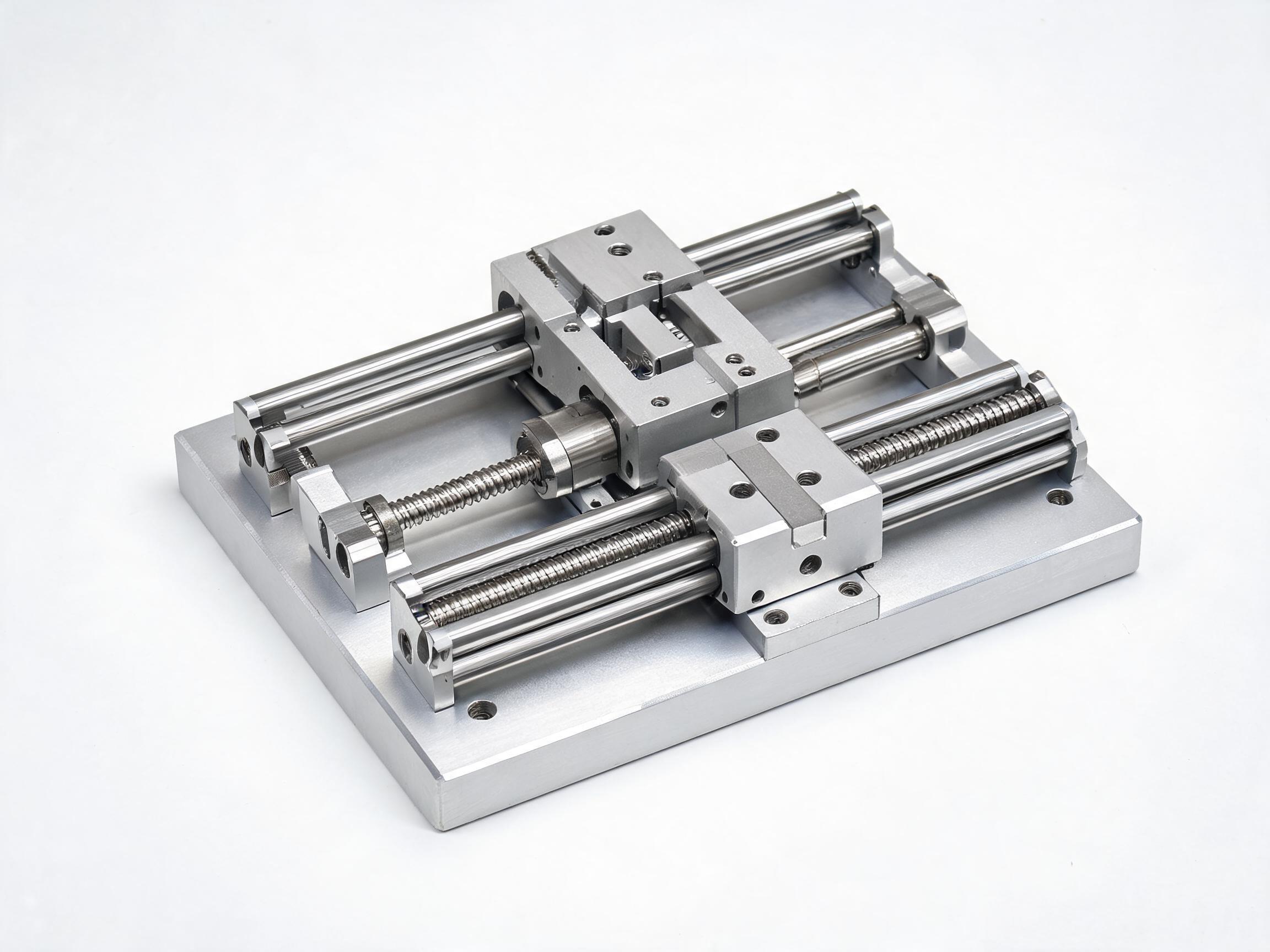
A practical, engineer-to-engineer guide for international buyers and design engineers who need to specify linear motion systems correctly. Covers the full architecture — linear bearings, guide rails, and ball screws — with selection criteria, load calculations, accuracy classes, and common specification mistakes. Written for B2B procurement decisions, not classroom theory.
BUYER GUIDE — LINEAR MOTION SYSTEMS
Linear Motion Bearing Systems: A Complete Selection Framework from Bearings to Rails to Screws
If you are sourcing linear motion components for a new machine design or replacing parts on an existing line, you already know the pain: too many catalogs, too many "equivalent" part numbers, and too little clarity on what actually drives performance and price. This guide gives you a practical selection framework — covering linear bearings, guide rails, and ball screws — so you can specify correctly the first time and avoid costly rework.
• Match the bearing type to the load direction — radial vs. moment loads change the choice entirely.
• Rail preload classes (C0–C3) directly affect rigidity and positioning accuracy; higher is not always better.
• Ball screw lead accuracy (C3–C10) and axial clearance determine whether your application needs a ground or rolled screw.
• For export orders, always confirm the tolerance class, lubrication type, and wiper material — these are the first things that cause field failures.
Why the "Bearing Only" View Fails
Many buyers focus on the linear bearing itself — the block or bushing — and treat the rail and screw as afterthoughts. That is a mistake. A linear motion system is three interacting components:
- The bearing (the moving block or bushing) that carries the load
- The rail (the guideway) that defines the path and absorbs forces
- The screw (or actuator) that converts rotary motion into linear travel
Each component has its own tolerance stack, and the system's final accuracy is the sum of all three. If you specify a high-precision screw but pair it with a loose-fit rail, you will not get the positioning repeatability your drawing claims.
Step 1: Define Your Load and Motion Profile
Before opening any catalog, write down four numbers:
- Maximum dynamic load (N or kgf) — peak force during operation, not average
- Maximum static load — force applied when the machine is stopped or during a crash condition
- Travel speed (m/min or mm/s) — determines whether you need ball or roller elements
- Duty cycle — strokes per minute and operating hours per day
These four numbers filter out 80% of unsuitable products immediately. For example, a high-speed pick-and-place machine with a 2-meter stroke and 60 cycles per minute needs a ball-type linear guide with a cage or roller retainer — not a plain bushing system that will overheat.
| Motion Profile | Recommended Bearing Type | Why |
|---|---|---|
| High speed, low load | Ball-type linear guide (LM guide) | Low friction, high travel speed |
| Heavy load, low speed | Roller-type linear guide | Higher rigidity, larger contact area |
| Compact, short stroke | Linear bushing (ball spline or shaft) | Simple design, cost-effective |
| High moment load | Wide rail with 4-row ball contact | Better moment capacity in all directions |
Step 2: Choose the Bearing Type
Linear Guide Blocks (LM Guides)
These are the most common choice for CNC machines, automation equipment, and precision stages. Key parameters:
- Number of ball rows: 2-row vs. 4-row designs. Four-row types (e.g., HGH, HGW series) handle moment loads better. Two-row types are lighter and faster.
- Ball vs. roller elements: Balls give lower friction and higher speed; rollers give higher rigidity and load capacity. If your application involves heavy cutting forces or intermittent shock loads, rollers are the safer choice.
- Preload class: C0 (no preload) to C3 (heavy preload). Higher preload increases rigidity but also increases friction and reduces service life. For general automation, C1 is a balanced default. For precision grinding or measuring machines, C2 or C3 may be required.
Linear Bushings
These are cylindrical bearings that slide on a hardened shaft. They are inexpensive and compact, but they have lower load capacity and accuracy than LM guides. Use them for:
- Light-duty pick-and-place units
- Printers and labeling machines
- Applications where the shaft is the structural member
Crossed Roller Bearings
For very high rigidity in a compact space — typically in rotary tables, indexing units, and precision turntables. They are not for general linear motion but for applications where the bearing must handle both radial and axial loads simultaneously.
Step 3: Select the Rail (Guideway)
The rail is the foundation. Its straightness, hardness, and mounting surface determine the system's real accuracy.
Rail Straightness and Accuracy Grades
Most manufacturers offer three accuracy grades: Normal (N), High (H), and Precision (P). The difference is in the permissible straightness deviation over a 1-meter length:
- Normal (N): ±10 µm/m — general automation
- High (H): ±5 µm/m — machining centers, wire cutters
- Precision (P): ±3 µm/m — measuring machines, semiconductor equipment
Buyer tip: For export orders, confirm the accuracy grade in writing. Many suppliers quote "equivalent to THK HSR" but deliver a normal-grade rail. Ask for the measurement report or specify the grade in your PO.
Rail Hardness and Material
Rails are typically made of bearing steel (SUJ2 / 100Cr6) hardened to HRC 58–62. The hardness matters because the rail surface is what the balls roll on. If the rail is soft, it will Brinell (dent) under load, and the bearing will fail prematurely.
For corrosive environments, specify a stainless steel rail (SUS440C or equivalent). It costs more but avoids rust contamination in food, medical, or chemical applications.
Rail Mounting
Check whether the rail is supplied with mounting holes (counterbored) or requires machining. Standard rails come with pre-drilled holes; long rails (over 3 meters) are often supplied un-drilled to allow the customer to match their bolt pattern. Confirm this with your supplier before ordering — it affects lead time significantly.
Step 4: Specify the Screw (Ball Screw or Lead Screw)
The screw converts rotary motion to linear motion. It is the component most often mis-specified.
Ball Screw vs. Lead Screw
- Ball screw: Uses recirculating balls between the screw shaft and nut. Low friction, high efficiency (90%+), suitable for continuous duty. This is the default for CNC and automation.
- Lead screw: Uses sliding contact (often with a plastic nut). Lower cost, quieter, but lower efficiency (30–50%) and higher wear. Suitable for light-duty, intermittent use, or where self-locking is required.
Key Ball Screw Parameters
- Lead (mm/rev): The linear travel per revolution. A 10 mm lead means 10 mm travel per turn. Higher lead = faster speed but lower resolution.
- Accuracy grade: C3, C5, C7, C10. C3 is the highest common grade (ground screw, ±5 µm/300mm). C7 is a rolled screw (±50 µm/300mm) — fine for general automation, not for precision positioning.
- Axial clearance: For precision applications, specify a preloaded nut (zero backlash). For general applications, a standard nut with 0.05–0.1 mm clearance is acceptable.
| Application | Screw Type | Accuracy Grade | Preload |
|---|---|---|---|
| CNC milling machine (Z-axis) | Ball screw, ground | C3 | Zero backlash (preloaded) |
| General pick-and-place | Ball screw, rolled | C7 | Standard (small clearance) |
| 3D printer / light lab equipment | Lead screw | — | Standard |
| Measuring / inspection stage | Ball screw, ground | C3 or better | Zero backlash |
Screw Support and End Fixing
The screw must be supported at both ends. The common arrangements are:
- Fixed-fixed: Best rigidity, for long strokes and high precision
- Fixed-supported: Good balance, most common for medium-length strokes
- Fixed-free: For short strokes and light loads only
If your stroke exceeds 1.5 meters, do not use fixed-free. The screw will whip at speed and the positioning error will be unacceptable.
Step 5: Lubrication and Seals — The Often-Forgotten Third Factor
A well-specified bearing system will fail early if lubrication and sealing are wrong.
- Grease vs. oil: Grease is simpler for most applications. Lithium-based grease (e.g., EP2) is standard. For food-grade applications, specify food-grade grease (NSF H1). For high-speed applications (DN value over 100,000), oil lubrication is required.
- Wipers/seals: Standard wipers (nitrile rubber) are fine for clean environments. For dusty or machining environments (wood, graphite, cast iron), specify a scraper-type seal or double wiper. This is a low-cost option that dramatically extends service life.
Step 6: Integration and Tolerance Stack
Once you have selected all three components, check the tolerance stack:
- Rail straightness (e.g., H grade: ±5 µm/m)
- Screw lead error (e.g., C5: ±18 µm/300mm)
- Bearing block height tolerance (e.g., ±10 µm)
The total positioning error is roughly the square root of the sum of squares (RSS) of these values. If your application requires ±20 µm positioning accuracy, a C5 screw with H-grade rail and standard block tolerance will be borderline. You may need to step up to C3 screw and P-grade rail.
Cost vs. Performance: Where to Spend and Where to Save
- Do not save on the rail: The rail is the reference surface. A cheap rail will ruin the accuracy of an expensive screw.
- Do not over-specify the screw: If your application is a simple transfer axis with ±0.1 mm tolerance, a C7 rolled screw is fine. Paying 3x for a C3 ground screw is wasted money.
- Do spend on seals: Wiper upgrades cost little and protect the entire system.
- Consider the mounting surface: A precision rail mounted on a poorly machined base plate will not perform to its grade. Confirm the flatness requirement with your machine shop.
FAQ — Quick Answers for Buyers
Q: Can I mix brands — e.g., a THK rail with a Hiwin block? A: Technically, the rail profiles are standardized (e.g., 15 mm, 20 mm, 25 mm widths), and many manufacturers' blocks will fit another brand's rail. However, the fit may not be exact, and the load rating and preload may differ. For critical applications, use the same brand for rail and block. For non-critical applications, confirm the interchangeability chart with your supplier before ordering.
Q: What is the typical lead time for linear motion components? A: Standard sizes (e.g., 20 mm rail, 16 mm screw) are often in stock. Non-standard lengths, custom accuracy grades, or stainless steel variants typically take 3–6 weeks. Ground screws with C3 accuracy can take longer. Confirm lead time at the RFQ stage, not after placing the order.
Q: How do I verify the quality of a supplier's linear bearings? A: Ask for three things: (1) the measurement report for straightness and lead error, (2) the hardness test report (HRC value), and (3) a sample for trial mounting. A reputable supplier will provide these without hesitation. If a supplier cannot provide basic test reports, treat that as a red flag.
Q: What is the service life of a linear bearing system? A: Life is calculated based on dynamic load rating (C) and applied load (P), using the formula L = (C/P)³ × 10⁶ revolutions (for ball screws) or L = (C/P)³ × 50 km (for linear guides). Most manufacturers provide a life calculation tool. As a rule of thumb, a properly selected and lubricated system should last 10,000–20,000 operating hours. If your application requires more, consider derating the load or upgrading the bearing size.
Final Checklist Before You Send the RFQ
- Load (dynamic and static) — in Newtons or kgf
- Travel speed and acceleration
- Stroke length
- Accuracy requirement (positioning and repeatability)
- Environment (dust, coolant, temperature, humidity)
- Lubrication type (grease or oil, food-grade or not)
- Mounting orientation (horizontal, vertical, inverted)
- Rail length and number of blocks per rail
- Screw lead and accuracy grade
- Shaft end machining (if the screw needs custom ends)
Providing these ten points in your RFQ will get you accurate quotes and reduce the back-and-forth with suppliers. It also signals that you are a professional buyer who expects technical competence — which tends to result in better pricing and service.
Need help selecting the right linear motion system for your application? Send us your load, stroke, and accuracy requirements — our engineers will recommend a matching configuration within one business day.