
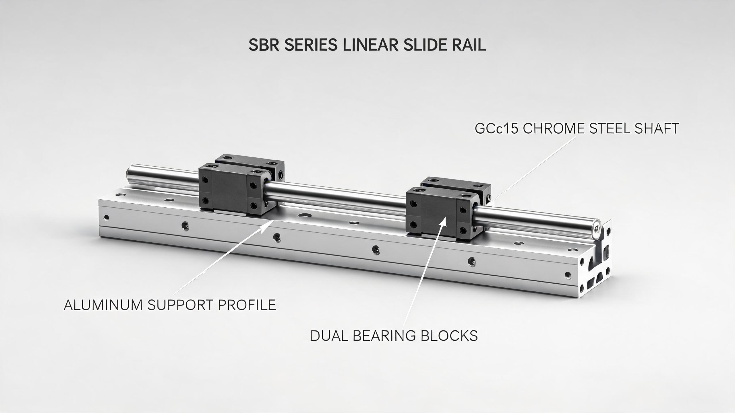
A practical engineering guide for B2B buyers and automation integrators evaluating the SKF20 aluminum profile slide table module. This article covers structural composition, load capacity ratings, assembly configurations, and integration considerations for linear slide rail guide systems in automated machinery.
AUTOMATION COMPONENT GUIDE
SKF20 Aluminum Profile Slide Table Module: Integration, Load Capacity, and Assembly Configuration for Automation Systems
When an automation integrator specifies a linear motion axis, the decision rarely comes down to the slide table alone. The real question is whether the module fits the machine's structural envelope, handles the cycle loads, and integrates cleanly with the rest of the drive train. The SKF20 aluminum profile slide table module is a compact, belt- or screw-driven linear axis designed for precisely that kind of application. This article breaks down its construction, load characteristics, and the assembly configurations you need to evaluate before writing a purchase order.
- The SKF20 module pairs an aluminum extruded profile body with a linear slide rail guide system, offering a balance of rigidity and weight reduction for medium-duty automation.
- Load capacity depends on orientation: horizontal, vertical, and side-mounted configurations yield different dynamic and static ratings.
- Belt-drive versions prioritize speed and travel; ball-screw versions prioritize positioning accuracy and thrust. Confirm which variant matches your cycle requirements.
- Integration points include motor mounting, sensor slots, and T-nut channels — verify these match your existing machine frame before ordering.
1. What the SKF20 Module Actually Is
The SKF20 is a ready-to-mount linear axis built around a 20 mm-series aluminum profile. The name "SKF20" typically refers to the profile width or the rail series, depending on the manufacturer. The module combines three core elements:
- Aluminum profile body — the structural backbone, extruded with T-slots for mounting and sensor placement.
- Linear slide rail guide — the recirculating ball bearing system that carries the carriage. This is the component that determines load capacity and travel accuracy.
- Drive mechanism — either a timing belt or a ball screw, housed inside the profile, converting rotary motor input into linear carriage motion.
The "20" in the name usually corresponds to the rail width or the profile series. It is a compact module, typically used in applications where space is limited but repeatability still matters.
2. Load Capacity: Reading the Ratings Correctly
Load capacity is the single most misread specification on any linear slide rail guide. The numbers printed in catalogs are not universal — they depend on orientation, mounting, and whether the load is static or dynamic.
Dynamic vs. Static Load
- Dynamic load rating (C) — the load that gives a defined service life (typically 50 km of travel) under constant operation. Use this for sizing in continuous cycling applications.
- Static load rating (C0) — the maximum load the bearing can withstand without permanent deformation. Use this for sizing in low-speed or stationary applications.
For the SKF20 module, the linear slide rail guide inside determines these values. A typical 20 mm rail with four recirculating ball blocks will have a dynamic load rating in the range of 6–10 kN and a static rating of 10–15 kN, depending on the block type and preload class. These numbers are for the rail guide itself — the actual module capacity is further limited by the drive mechanism and the profile's bending strength.
| Orientation | Typical Dynamic Load (kN) | Typical Static Load (kN) | Key Limiting Factor |
|---|---|---|---|
| Horizontal (flat) | 6–10 | 10–15 | Rail block capacity |
| Vertical (wall mount) | 4–7 | 8–12 | Moment load on carriage |
| Inverted (ceiling) | 3–6 | 6–10 | Belt tension / screw buckling |
ENGINEERING NOTE
Moment Loads Matter More Than You Think
Most SKF20 failures in the field are not from exceeding the vertical load rating. They come from moment loads — the torque generated when the load center is offset from the carriage center. A 20 mm rail has a limited moment capacity in the pitch, roll, and yaw axes. If your tooling extends 100 mm beyond the carriage center, the effective moment load can exceed the rail's rating even with a modest payload.
Rule of thumb: Keep the load center as close to the carriage as possible. If you cannot, calculate the moment (force × distance) and compare it against the rail's moment ratings — not just the vertical load rating.
3. Drive Mechanism: Belt vs. Ball Screw
The SKF20 module is available in two main drive configurations. Each changes the module's performance envelope significantly.
Belt-Driven SKF20
- Speed: Up to 2–5 m/s, depending on pulley ratio and motor.
- Accuracy: Positioning repeatability typically ±0.05 to ±0.1 mm.
- Travel length: Can be longer, as belt drives do not suffer from screw whip.
- Thrust: Limited by belt strength and tooth shear — typically lower than screw drives.
Best for: Pick-and-place, gantry axes, packaging machinery, and any application where speed and travel length matter more than sub-millimeter precision.
Ball-Screw-Driven SKF20
- Speed: Limited by critical screw speed (typically 0.5–1 m/s for longer travels).
- Accuracy: Repeatability of ±0.01 to ±0.03 mm is achievable.
- Travel length: Limited by screw buckling — beyond ~1,000 mm, screw diameter must increase.
- Thrust: Higher, as ball screws convert rotary motion to linear force more efficiently.
Best for: CNC loading, precision positioning, dispensing, and applications requiring high thrust at low speed.
4. Assembly Configurations and Integration Points
The SKF20 aluminum profile is designed for modular integration. The profile's T-slots serve multiple purposes: mounting the module to a machine frame, attaching sensors, and securing cable carriers.
Motor Mounting
The motor mounts to a flange at one end of the module. For belt-driven versions, the motor can be mounted inline or parallel (via a timing belt reduction). For ball-screw versions, the motor mounts directly to the screw shaft or through a coupling. Confirm the motor flange size (NEMA 23, NEMA 34, or metric equivalent) matches your existing motor inventory.
Sensor Slots
The profile typically includes one or two longitudinal slots for proximity sensors or limit switches. These are used to define home position and travel limits. The sensor type (PNP/NPN, 5V/24V) must match your controller's I/O specifications.
Carriage Mounting
The carriage has a pattern of threaded holes (typically M5 or M6) for attaching your tooling or payload plate. The hole pattern varies by manufacturer — verify the pattern matches your existing tooling plates, or budget for an adapter plate.
Cable and Hose Management
For moving cables or air hoses, the profile can accommodate a cable carrier (energy chain) mounted to the side or top. The T-slots provide the mounting points for the carrier brackets. Plan for this during the design phase — retrofitting a cable carrier after installation is labor-intensive.
5. Load Capacity in Real Applications
A common mistake is sizing the SKF20 module based on the static load rating alone, then discovering that the dynamic loads at speed cause premature wear. Here is a practical sizing workflow:
- Calculate the total moving mass — carriage + payload + tooling.
- Determine the acceleration profile — the peak acceleration during the cycle.
- Calculate the dynamic force — F = m × a, plus any process forces (cutting, pressing, dispensing).
- Compare against the dynamic load rating — apply a safety factor of 1.5–2 for industrial use.
- Check the moment loads — if the payload center is offset, calculate the moment and compare against the rail's moment ratings.
If your application exceeds these values, you have three options: move to a larger profile series (e.g., SKF25 or SKF30), add a second rail for parallel support, or reduce the acceleration profile.
6. Environmental and Compliance Considerations
The SKF20 module is an aluminum-profile-based system. Aluminum offers good corrosion resistance, but the steel linear slide rail guide and ball bearings require protection in harsh environments.
- Standard version: Suitable for clean, dry, indoor environments (assembly, packaging, electronics).
- Dusty environments: Specify wiper seals on the rail blocks and consider a bellows cover for the profile.
- Washdown / food processing: Verify the manufacturer offers stainless steel rail options or a fully sealed version. Standard carbon steel rails will corrode in washdown environments.
For export to the EU, verify that the module's materials comply with RoHS and REACH directives if your end product requires it. For machinery safety, the module itself is a component — the machine builder is responsible for CE marking of the complete machine per the Machinery Directive.
7. What to Confirm with the Supplier Before Ordering
Before sending an RFQ for an SKF20 module, have the following information ready:
| Item | Why It Matters |
|---|---|
| Travel length (mm) | Determines profile length and screw/belt sizing. |
| Required thrust (N) | Determines whether belt or screw drive is suitable. |
| Positioning accuracy (mm) | Belt: ±0.05–0.1; Screw: ±0.01–0.03. Confirm your tolerance. |
| Motor type and flange | NEMA or metric; flange size must match module's motor mount. |
| Operating environment | Dust, washdown, temperature — affects wipers, seals, and material choice. |
| Cycle life target | Required travel distance over the machine's life — used to calculate dynamic load margin. |
If the supplier cannot provide load ratings, moment ratings, or material certifications in writing, treat that as a red flag. A reputable manufacturer will supply a datasheet with these values.
8. Cost vs. Performance: Where the SKF20 Fits
The SKF20 sits in the medium-duty segment of linear motion. It is more compact and lighter than a 25 mm or 30 mm profile system, which makes it attractive for OEMs building multi-axis gantries where weight and inertia matter. It is also typically more cost-effective than a precision ground rail system, while still offering adequate accuracy for most automation tasks.
Where it excels:
- Multi-axis pick-and-place robots
- Test and inspection stations
- Dispensing and soldering axes
- Light assembly automation
- Laboratory and medical device automation
Where it is not suitable:
- Heavy machining (use a box-way or heavy-duty linear guide)
- Sub-micron positioning (use a cross-roller or air bearing stage)
- Extreme environments without proper sealing
FAQ
Q: Can I mount the SKF20 module vertically? A: Yes, but derate the load capacity. The carriage must handle the moment load from the payload's weight and any off-center tooling. Confirm the moment ratings with the supplier.
Q: What is the maximum travel length for the SKF20? A: Belt-driven versions can reach 3,000 mm or more. Ball-screw versions are typically limited to 1,000–1,500 mm before screw whip becomes an issue. Confirm the critical speed calculation with the manufacturer.
Q: How do I choose between belt and screw drive? A: If you need speed and long travel, choose belt. If you need thrust and precision, choose screw. If you need both, discuss a hybrid solution with the supplier.
Q: Does the module come with a motor? A: Usually not. The module is sold as a mechanical axis. You select the motor, driver, and controller separately, based on your control architecture. Some suppliers offer integrated servo kits — ask if available.
Q: What is the typical lead time? A: Lead times vary by manufacturer and configuration. Standard lengths with common drive options are often stocked. Custom lengths or special sealing options typically add 2–4 weeks. Confirm at the time of quotation.
The SKF20 aluminum profile slide table module is a practical choice for medium-duty automation when you need a compact, modular linear axis. The key to a successful integration is not just picking the module — it is matching the drive type, load ratings, and assembly configuration to your specific cycle requirements. Start with the load calculation, confirm the moment ratings, and verify the integration points with your supplier. That sequence will save you from the most common field failures.
For a detailed quotation or to discuss your specific application, contact our engineering team with your travel length, payload, and accuracy requirements. We can provide a datasheet and a load calculation for your application.