
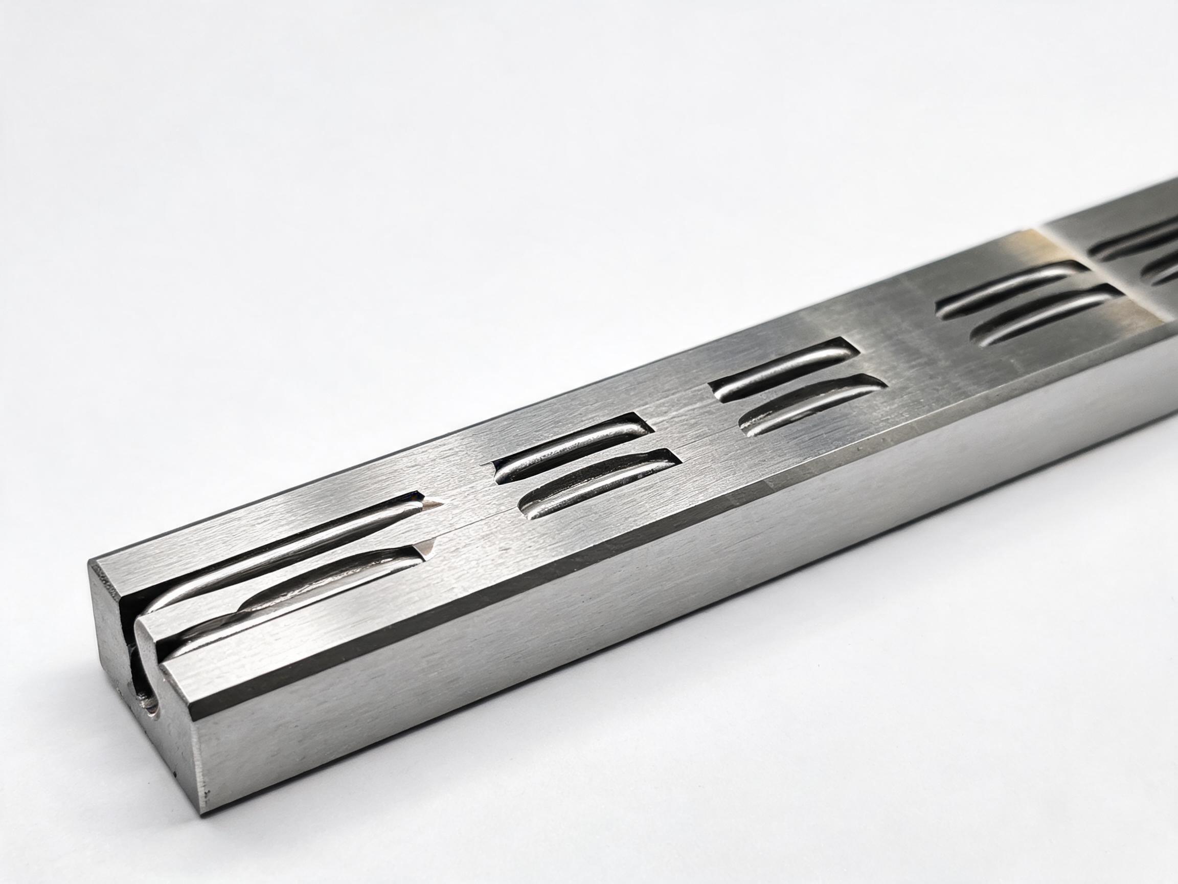
Rail accuracy class tells you how straight the rail is; it says nothing about the surface you bolt it to. This article explains how an out-of-flat mounting base changes preload and carriage loading, what symptoms appear at the machine (corner rocking, uneven running resistance, local preload loss), three practical ways to deal with it, and which flatness figures to request from your supplier before ordering.
Installation Planning
A rail datasheet can promise a very straight rail and still leave you with a rough-running axis, because the rail is only half of the geometry. The other half is the surface you bolt it to. This article is about that mounting base — how flat it needs to be, what happens when it is not, and what to ask suppliers before the order is placed.
Buyers searching for linear guide rail flatness usually already have a rail selected. What they do not have is a number for the base plate or machine bed, and the catalogue does not appear to provide one. That gap is real: rail accuracy class, rail straightness and mounting-surface flatness are three separate specifications, and only the last one belongs to your frame, not to the rail supplier.
Key takeaways
- Rail accuracy class describes the rail; base flatness describes your machine. One never substitutes for the other.
- An out-of-flat base is absorbed as local deflection of the rail and carriage interface — it shows up as preload loss and uneven contact, not as a visible bend in the rail.
- Self-aligning carriages such as the HGW series (±0.5°) can absorb small installation errors, but they are not a substitute for machining the base.
- There is no universal “base must be ≤ X mm/m” figure. The requirement is written per the datasheet of the selected rail size and preload class, and confirmed with the supplier.
Three different numbers that buyers often merge into one
Before discussing what happens to an out-of-flat base, separate the specifications. They are measured on different parts, by different parties, and one cannot compensate for another.
- Rail accuracy class — the grade of the finished rail itself (for example H or P5 on a ground HGR45 rail). This is a manufacturing tolerance on the rail.
- Rail straightness — how much the rail deviates from a straight line along its length. On a ground HGR45 rail, the production process holds raceway flatness within 5 µm and straightness within 0.02 mm/m.
- Mounting-surface flatness — the flatness of the machine bed, base plate or spacer you bolt the rail onto. This is the number the machine builder owns, and the one this article addresses.
A rail that is straight to 0.02 mm/m will follow whatever the base does. Bolt it to a base that twists, and the rail twists with it — the rail has not failed, it has been conformed to the mounting surface.
What an out-of-flat base actually does to preload and carriage load
Preload is set by the fit between the rolling elements and the raceways — it is a controlled interference built into the rail/carriage pair. The carriage is stiff, and its four rows of balls or rollers share load in a fixed pattern. When the base deviates from flat, the rail is forced into a gentle wave. Because the carriage is short compared with the wavelength of that wave, the carriage sees it as a tilt rather than as a curve.
That tilt changes the load distribution inside the carriage: two diagonal rows take more load, the other two take less. In a preloaded system this does not remove the preload uniformly — it redistributes it. Some contact zones gain preload and run hotter; others lose it and lose stiffness in that direction. The rail is fine. The bearing interface is being asked to absorb geometry that should have been machined into the frame.
Symptoms that point to the base, not the rail
These are the field symptoms that usually lead a buyer back to the mounting surface. They are worth recognising early, because the instinct is almost always to blame the rail.
- Corner rocking on the carriage. With the carriage unloaded, a light hand pressure on each corner of the block produces visible or audible movement on some corners and not others. The cause is local loss of preload where the rail has been pushed out of contact by the base deviation.
- Uneven running resistance. Pushing the carriage along the rail, drag changes along the stroke — heavy at certain positions, light at others, with a repeatable pattern. It often correlates with bolt-hole positions or with a joint between two base plates.
- Local preload loss and clearance. The axis feels tight at one end and slightly loose at the other. This is the same mechanism expressed in stiffness: one region of the stroke has effectively less preload than the design intent.
- Noise and vibration under load. A carriage cycling through a region of low contact can run noisier and transmit more vibration to the structure at those positions.
- Uneven wear and position error. Over time, the contact zones that carry extra load show it. Repeatability suffers before anything visibly breaks.
None of these are proof of a defective rail. All of them are consistent with a base that is not flat enough for the preload class specified.
Three ways to deal with a base that is not flat enough
1. Machine the mounting base to the required flatness
This is the default for production machines and the only approach that scales to repeat builds. The base is machined, ground or milled and then checked against the flatness figure on the rail datasheet for that size and preload class. The figure varies with rail size, preload and application stiffness requirements, so it is taken from the datasheet and confirmed with the supplier rather than assumed from a general rule. Machining is the most expensive option per unit at first build and the cheapest over the life of the product, because it removes the variable entirely.
2. Correct locally with shims or spot scraping
For retrofits, single machines, or bases where full remachining is not practical, local correction is a legitimate route. Thin shims under the rail at the low points, or spot scraping (hand-scraping high spots) with a straightedge and a flatness check after each pass, can bring a base into an acceptable range. The discipline matters more than the method: measure, correct, re-measure with the rail in place. Local correction is easy to do badly, and a poor shim job trades one flatness problem for a rail that is no longer supported evenly along its length.
3. Use the carriage's self-aligning capability — within limits
Wide-body carriages such as the HGW series offer a self-aligning capability of ±0.5°, which absorbs small installation errors in the mounting surface and helps in applications where perfect base geometry is not achievable. That ±0.5° is a useful margin, not a design allowance for a warped bed. Self-alignment works over a small angular error; a base with a long-wave twist or a step at a plate joint produces errors that repeat along the stroke, and no carriage can average those out.
Keeping support spacing sensible supports this approach: the closer the mounting bolts, the less the rail is free to conform to the base between them, and the more of the error the carriage has to absorb. Rail bolt pitch is fixed by the rail — on HGR45, bolt holes are on a 60 mm pitch with M12 fasteners — so the practical lever is the flatness of the base between those bolts and the structure supporting it.
Why the rail itself is rarely the limiting factor
Take a ground HGR45 rail as a reference point. The rail body is high-carbon steel with induction-hardened raceways at 58–62 HRC, and the grinding process holds raceway flatness within 5 µm and straightness within 0.02 mm/m, in standard lengths up to 4000 mm. That is a stiff, precise, well-supported part. When an axis built on such a rail runs unevenly, the rail has usually done exactly what it was asked to do: it has taken the shape of its mounting surface.
The same logic applies across the HGR series: the rail is manufactured to a straightness and raceway tolerance, and the installation geometry is the buyer's responsibility. Spending more on a higher accuracy class does not fix a base that is out of flat — it simply means you paid for rail precision the frame will not let you use.
What to confirm with the supplier before ordering
These are the questions that turn a vague concern about flatness into a specification you can machine to and inspect against. Ask them while the design is still open.
| Item to confirm | What you need to know | Why it matters |
|---|---|---|
| Required base flatness for your rail size and preload | The flatness figure stated per the datasheet for the selected rail and preload class | This is the number your machining drawing needs; it changes with size and preload |
| Whether the figure is for one rail or a pair | Flatness of a single base surface versus height and parallelism between two rails | The two rails of an axis have a separate alignment requirement from base flatness |
| Measurement method | Straightedge, dial indicator on a carriage, or surface plate — and over what length | A figure without a method is not inspectable at goods-in or at build |
| Preload class and its sensitivity | How much preload the selected class carries, and how much surface error it tolerates | Higher preload classes are less forgiving of base deviation |
| Self-aligning allowance, if applicable | Whether the carriage model provides self-alignment and within what angle | Lets you plan the base spec with a known margin instead of guessing |
| Rail joint and splice handling | How butt joints between rail lengths are specified | Joints are common locations for local flatness and alignment steps |
Two of these deserve emphasis. First, ask for the flatness requirement as a written figure per the datasheet, not as a general statement that the base “should be flat”. Second, ask what measurement method the figure assumes. A flatness tolerance that nobody can check on the shop floor is not a useful tolerance.
A practical sequence for the machine builder
- Select the rail size and preload class first, then request the base flatness figure for that combination.
- Put the figure and the measurement method on the base-plate drawing, with the datum and inspection length stated.
- Machine or correct the base, then check it before the rail goes on.
- After mounting, check running resistance along the full stroke and test for corner rocking with the carriage unloaded.
- If a deviation is found, fix the base — not the preload class.
Bottom line: rail accuracy class and rail straightness describe what the supplier delivers; base flatness describes what your machine contributes. Both must be specified, and only one of them is fixed by buying a better rail. Match the base to the datasheet figure for the rail and preload you have chosen, and keep the self-aligning margin of the carriage as margin — not as the plan.
If you are confirming a rail and carriage combination for a new axis, send the rail size, preload class, stroke length and mounting arrangement, and the supplier can tell you which flatness figure applies to your base.