
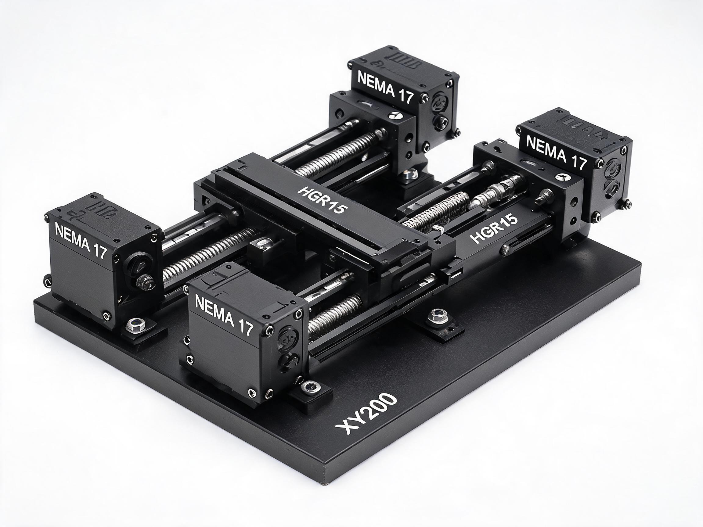
A practical guide to reading stroke length on a linear module datasheet. Learn to separate stroke, travel, envelope and screw length, using the XY200 precision cross-slide table's listed specifications as a worked example.
Datasheet Reading Guide
A linear module datasheet can list four different lengths for the same machine: stroke, travel, envelope and screw length. They are not interchangeable. If you compare them as if they were, you will either order a module whose table cannot reach the parts you designed it for, or you will overbuild the frame to fit a stroke number you did not actually need. This guide shows how the numbers relate, what determines them, and how to put a stroke requirement on a purchase order so the manufacturer and the buyer are working from the same dimension.
Stroke and travel: the difference most datasheets blur
On many linear modules, the datasheet uses "stroke" to describe the nominal distance the carriage is designed to move, while "travel" or "effective travel" describes the distance the carriage can actually move once the nut, motor mount, limit switches and end machining are installed. The two are different because hardware occupies space that would otherwise be travel.
A ball screw module is driven by a screw and a nut. The nut blocks a section of the screw, so the carriage cannot ride through that section. The motor mount and the end supports also sit at the extremes of the screw. That means the effective travel of a module is shorter than the screw length can suggest, and any figure taken from the overall length of the screw will overstate what the table can do.
Limit switches and end-stop hardware, when fitted, take additional travel from the extremes. The same nominal stroke on a module with limit switches at both ends will have less usable travel than a bare version. The exact figure depends on the specific build, so the safe rule is to treat stroke, travel and screw length as three separate numbers and read the datasheet values for each. Where the datasheet lists only one of them, confirm per datasheet with the supplier.
Machine envelope is not stroke
The overall envelope describes the outer physical size of the module, including the base plate and the motor mount and any covers or end plates. Stroke describes the movement the carriage offers inside that envelope. A module with a 300 mm envelope does not necessarily have a 300 mm stroke, and ordering a module by its envelope will leave you short of travel.
Confusing the two creates a second problem: a designer may decide the machine envelope is the constraint and then ask for a stroke that matches it. The result is a module that is physically larger than the drawing allows. Read the envelope as the space you need to reserve on the frame, and the stroke as the reach of the moving carriage. Confirm both figures per datasheet before you commit a frame design.
Screw length, lead and the relationship to travel
The lead of the screw is the axial distance the nut travels per revolution. A 5 mm lead means one full turn moves the nut 5 mm, so a 200 mm stroke requires a corresponding number of turns. Lead does not equal stroke, and it does not directly set stroke. It determines how many motor revolutions produce the requested travel and therefore informs how the motor and any encoder are configured.
The screw length, in turn, sets how much threaded shaft is available for the nut and its travel range. A screw that is longer than the stroke gives mounted hardware and end supports enough shaft to sit on. A screw cut exactly to the stroke length may not allow the nut to reach the end positions once end machining, the support bearing, and the motor mount are fitted. The datasheet's stroke figure is the number to design to; the screw length is the number to inspect when verifying that the module can be installed.
Worked example: reading an XY200 datasheet
The XY200 Precision Cross Slide Table gives a clear case. Its listed specifications describe a precision cross-slide table with two axes, each driven by a ball screw and a linear rail carriage.
| Item on the datasheet | Listed value | What it tells the reader |
|---|---|---|
| Standard stroke per axis | 200 mm | Design target for movement on each axis |
| Custom stroke range | 100 mm to 500 mm | Range offered for custom builds |
| Ball screw drive | Dual SFU1605 C7, 5 mm lead | Screw type and lead per revolution |
| Linear rail | HGR15 with HGH15CA carriages | Guide format and carriage type |
| Overall envelope | 340 × 340 × 60 mm | Footprint of the table as built |
| Repeatability per axis | ±0.01 mm | Positional repeatability of each axis |
| Base plate flatness | Within 0.01 mm over 300 × 300 mm | Reference surface flatness |
| Perpendicularity | 90° ± 0.02° (verified by CMM) | Axis alignment tolerance |
| Motor mount | NEMA 17 | Accepted motor frame size |
| MOQ | 20 pcs standard, 15 pcs custom | Minimum order quantity |
On this datasheet, the 200 mm standard stroke and the 340 × 340 × 60 mm envelope are listed separately. That separation is the point. The 340 mm face of the table is the size the designer reserves in the frame; the 200 mm stroke is the movement available to the carriage. The two numbers are not the same, and a designer who uses the 340 mm figure as the stroke will overestimate reach. Conversely, a designer who assumes the 200 mm stroke means the whole table takes 200 mm in each direction will leave too little room for the base plate and motor mount.
The dual SFU1605 C7 ball screws with 5 mm lead tell you how the motion is transmitted. C7 designates a rolled screw tolerance class for the SFU ball screw construction; the SFU Series Rolled Ball Screw Assembly page describes that assembly family. The 5 mm lead means each full motor revolution advances the nut by 5 mm; read the module's control settings and motor configuration per datasheet for the resulting resolution.
The remaining listed values — repeatability of ±0.01 mm per axis, base plate flatness within 0.01 mm over 300 × 300 mm, and perpendicularity of 90° ± 0.02° verified by CMM — describe positioning and geometry. They do not describe stroke. Mixing precision figures with stroke figures is a common reading error; keep them in separate boxes in your design notes.
The XY200 datasheet's 200 mm standard stroke and 100–500 mm custom range are the listed values. For other values, confirm per datasheet.
How to specify stroke on a purchase order
Once you have read the datasheet, the next step is to write a requirement the supplier can quote against. A clear requirement does three things: it names the axis count, gives the required stroke per axis, and states whether the figure is standard or custom.
A practical statement for a two-axis table looks like this: "Two-axis cross-slide table, 200 mm stroke per axis, both axes. If 200 mm is available as a standard build, supply the standard configuration; if a different stroke is needed, quote against a custom stroke within the listed range." This wording distinguishes a standard request from a custom request, so the quotation reflects the correct MOQ and build. It also gives the supplier a clear fallback if the requested figure is not available at the standard build.
For the XY200, the standard stroke is 200 mm per axis and custom strokes are available from 100 mm to 500 mm. MOQ is 20 pcs for the standard build and 15 pcs for the custom build. If your required stroke is outside the listed range, state the required figure and ask the supplier to confirm whether the build is possible, because the 100–500 mm range is the listed custom offering, not an open-ended limit.
A short specification checklist
- State the stroke required per axis, not the overall envelope.
- State whether the stroke is the standard build or a custom figure.
- State the number of axes and whether the axes need separate stroke figures.
- Name the motor mount if the motor is supplied separately; the XY200 datasheet lists a NEMA 17 mount, and the motor itself is a separate item.
- Ask the supplier to confirm the effective travel and the envelope for the quoted build, since these can differ from the standard figures when custom stroke, limit switches or end machining change the build.
The reason to ask for both figures in the quotation is that the envelope and effective travel on a custom build can differ from the standard values. The listed 340 × 340 × 60 mm envelope and 200 mm standard stroke apply to the standard XY200 build; a custom stroke changes the build and may change the envelope and travel figures in ways the standard datasheet does not list. Confirm those figures per datasheet before using them in a frame design.
A purchase order that distinguishes standard from custom stroke, and envelope from stroke, arrives at the quotation stage with fewer questions. That saves a round of clarification and reduces the chance of a module that fits the frame but cannot reach the tool position.
Frequently asked questions
Does a 200 mm stroke mean the carriage moves 200 mm?
On the XY200, the listed standard stroke is 200 mm per axis. Effective travel can be shorter than the screw length because the ball nut, motor mount, limit switches and end machining use some of the available range. The datasheet figures for stroke and effective travel should be read separately, and any other travel value should be confirmed per datasheet.
Is the 340 × 340 × 60 mm envelope the stroke?
No. The XY200 lists a 340 × 340 × 60 mm overall envelope and a 200 mm standard stroke per axis as separate specifications. The envelope describes the physical footprint; the stroke describes carriage movement. Using the envelope as the stroke overestimates reach.
What is the screw lead on the XY200 and how does it relate to stroke?
The XY200 uses dual SFU1605 C7 ball screws with a 5 mm lead, so one full motor revolution advances the nut 5 mm. Lead describes motion per revolution; it does not set the stroke figure. The listed standard stroke is 200 mm per axis, with custom strokes from 100 mm to 500 mm available.