
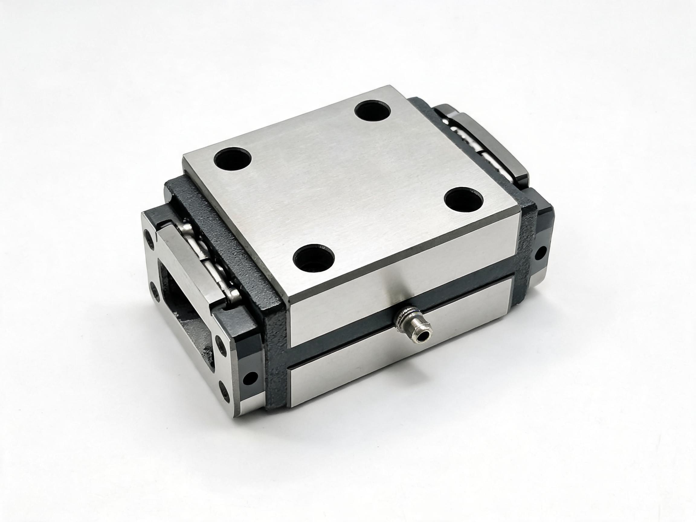
Machine builders planning faster axes need to know what limits a linear guide rail at speed and which specifications to state. This article explains ball recirculation behaviour, heat and lubrication film, seal drag and preload in qualitative terms, then shows the specification choices that matter: preload grade, sealing arrangement, lubrication port and re-greasing reference, and the rail oil-groove channel. It notes that speed limits depend on size, load, lubrication and sealing and must be confirmed against the datasheet.
High Speed Linear Guide Rails: What Actually Limits Speed
If you are planning a faster axis, the useful question is not “how fast can a guide rail go” in the abstract. It is which parts of the carriage-and-rail system set the practical ceiling for your size, load, lubrication and sealing arrangement — and which of those you can specify. The speed limit of any HGH/HGR combination depends on those variables and has to be confirmed against the datasheet for the chosen size and configuration; treat the discussion below as the reasoning behind that number, not a substitute for it.
What this article covers
- Ball recirculation and the reversing point
- Heat, lubrication film and seal drag
- Preload as a speed choice
- Specification table: what to state
- Rail features that help at speed
Key takeaways
- Speed limits are a function of size, load, lubrication and sealing, not a single catalogue constant.
- Ball recirculation and the reversal of ball direction are a principal source of drag, noise and heat at speed.
- Preload grade changes stiffness and drag together; C0, C1 and C2 are not interchangeable at high speed.
- Seals keep contamination out but add drag; lubrication supply has to keep up with the heat generated.
- Confirm the allowable speed for your specific size and preload against the datasheet.
Why “high speed” is a system question, not a rail number
A linear guide rail does not have one speed. The same rail profile can carry a lightly loaded carriage slowly with heavy preload and run a lighter preload faster with the same envelope, because the limiting mechanisms change with the operating conditions. Machine builders planning faster axes usually discover that the constraint appears somewhere other than the rail itself: in how the balls turn around at the end of the circuit, in how much lubricant reaches the contact, in how much drag the seals add, and in how much preload the application actually needs.
That is why a supplier’s speed figure is only meaningful when it is attached to a size, a load, a lubrication method and a sealing arrangement. The product records for the HGH and HGR series do not carry a standalone speed value for that reason, and any buying decision should rest on the datasheet figure for the exact combination you intend to run.
The physical limits at speed
Ball recirculation behaviour
In the HGH series carriage, a four-row ball recirculation circuit carries radial, reverse-radial and both lateral loads simultaneously. Each ball travels through the loaded zone, then enters the return path and is turned around at the ends. As travel speed rises, the ball has to reverse direction and re-enter the load zone more frequently per unit of distance, and the impact and acceleration at the reversing points become the dominant dynamic event in the carriage. That is where drag, noise and local contact stress concentrate. It is also why the geometry of the return circuit, rather than the rail alone, sets much of the practical ceiling.
This is a qualitative statement: the higher the speed, the more the recirculation event matters relative to steady rolling. It is one reason a rail-and-carriage selection for a fast axis should be confirmed against the datasheet rather than extrapolated from a slow application.
Heat and the lubrication film
Every source of drag in the carriage converts to heat, and heat thins the lubricant film at the ball contacts. A thin film raises friction further, which raises heat again. At speed the balance point between lubricant supply and heat removal is what keeps that loop from running away. The HGH carriage is supplied with a lubrication port on the top face that accepts standard M6 grease nipple fittings or a central lube line connector, so a machine builder can choose between manual re-greasing and a connected lube line depending on how accessible the axis is.
Lithium-based grease of NLGI Grade 2 is suitable for most applications. The re-greasing starting reference is every 100 km of travel or every 3 months, whichever comes first — and the record explicitly depends that interval on travel speed, load and environment. A faster axis consumes the reference distance sooner; that is exactly why the interval is a starting point rather than a fixed rule.
Seal drag
The HGH carriage uses an end seal plus a side seal strip, described in the record as IP40 equivalent. Sealing protects the ball circuit from chips, dust and coolant, but the lip contact that does the protecting also adds friction. At low speed this drag is a minor line item; at high speed the seal is in continuous sliding contact and its contribution scales with travel. The practical specification choice is therefore not “seal or no seal” but how much protection the environment demands and whether the resulting drag is acceptable against the heat and lubrication budget.
Preload
Preload removes clearance and raises stiffness, but it also raises the normal force at every ball contact, and with it friction and heat. The HGH series offers preload grades C0 (clearance), C1 (light) and C2 (medium). Choosing the stiffest grade by habit is not a speed decision; it is a stiffness decision that has a speed cost. The record notes that C0 suits high-speed linear transfer systems where noise is a concern, which is consistent with the mechanism above: less preload means less contact force to generate noise and heat at the recirculation event. Whether C0 is acceptable for your axis depends on the stiffness and accuracy the machine needs, so it is a judgement to make against the datasheet rather than a default.
Specification choices that matter
The table below maps the variables above onto the specification decisions a machine builder can actually state on a purchase request. It is a checklist for the conversation with the supplier, not a replacement for the datasheet figure.
| Specification point | What it controls | What to state on the request |
|---|---|---|
| Preload grade | Stiffness versus friction, heat and noise at speed | C0, C1 or C2, with the stiffness or accuracy requirement that drives it |
| Sealing arrangement | Contamination protection versus drag | End seal and side seal strip required (IP40 equivalent), and the environment (chips, dust, coolant) |
| Lubrication method | Whether the film keeps up with heat at speed | Manual re-greasing through the M6 port or a central lube line; NLGI Grade 2 lithium-based grease as the baseline |
| Re-greasing interval | Reliability across the duty cycle | Starting reference of every 100 km or every 3 months, whichever comes first, corrected for speed, load and environment |
| Rail lubrication retention | Film continuity between re-greasing points, especially on vertical axes | HGR series rail with its continuous oil-groove channel |
Preload is a speed choice, not a default
It is worth restating because it is the specification decision most often made by habit. If an axis is planned for faster travel and the accuracy requirement does not force a stiffer grade, C0 or C1 is where the drag budget leaves room. If the process needs C2 stiffness, then the heat and lubrication budget has to be checked against the datasheet speed for that grade rather than assumed.
Lubrication has to be specified as a system
Selecting the grease and the port is only half of it. The re-greasing reference of every 100 km or every 3 months is tied to travel speed, load and environment, so a faster axis shortens the interval in practice. A central lube line connector at the carriage top face makes that easier to hold on an axis that is hard to reach, and it is the reason the port is worth specifying deliberately rather than accepting whatever is fitted by default.
The rail side of the lubrication problem
The HGR series rail carries a continuous oil-groove channel that runs its full length and retains a lubricant film between re-greasing intervals. This matters most on vertical-axis installations, where gravity drains surface lubrication away quickly and the film on the rail can be the difference between smooth travel and metal-to-metal contact between service points.
Mounting tolerance and the load arrangement
Two interface facts are easy to overlook when the priority is speed. The HGH carriage’s self-aligning tolerance of plus/minus 0.5 degrees absorbs minor rail mounting errors without preload loss, which keeps the intended preload grade — and therefore the intended friction behaviour — from being changed by installation. And the four-row recirculation circuit carries radial, reverse-radial and both lateral loads simultaneously, so moment and side loads do not require a separate load rating for each direction when you are sizing the axis.
What to confirm before you commit
- The datasheet speed figure for the exact size, preload grade, load and lubrication method you intend to use. There is no substitute for this step.
- Whether your environment requires the end seal and side seal strip, and what drag that adds at your travel speed.
- Whether manual re-greasing or a central lube line fits your machine access and service schedule.
Product pages referenced in this article:
HGH series flange-type linear guideway carriage block — four-row recirculation, preload grades C0/C1/C2, M6 lubrication port, end and side seals.
HGR series heavy-duty linear guideway rail — continuous oil-groove channel for lubricant retention along the full rail length.
Speed capability depends on size, load, lubrication and sealing. The figures in this article describe mechanisms and specification choices; the allowable speed for a given configuration must be confirmed against the datasheet for that exact size and preload grade.