
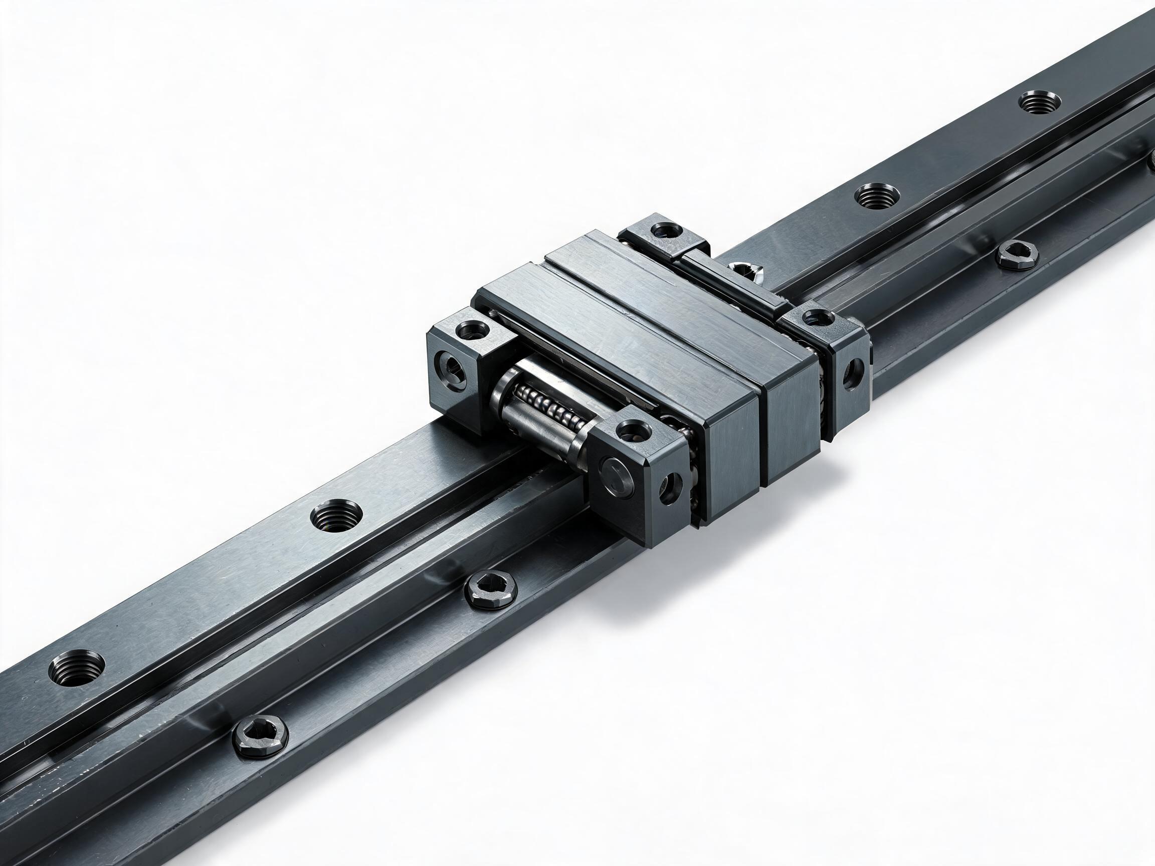
A specification checklist for robot integrators selecting linear guides for floor-mounted transfer units and 7th-axis rails: load direction, heavy-duty sizing, long-travel rail jointing, mounting, and lubrication, grounded in HGR series and HGR45 data.
A robot transfer unit moves a robot between stations, and its linear guide rail carries loads that a normal working axis does not see: the robot's mass overhung at different reach positions, acceleration from each carriage, and the moment created when the arm extends off the rail. The guide specification that follows is a checklist for integrators and automation engineers, built on HGR series and HGR45 data, so the rail, carriage, jointing, mounting and lubrication all match the duty the transfer unit actually imposes.
Key takeaways
- The four-row ball circuit of the HGR series carries radial, counter-radial and lateral loads simultaneously — the arrangement a transfer unit needs when the robot loads the axis from multiple directions.
- HGR45 is the heavy-duty reference point in this series: 45×38 mm rail cross-section, 6.2 kg/m, M12 bolts at 60 mm hole spacing, and a paired HGW45CA carriage rated 62.8 kN dynamic / 112 kN static.
- Standard HGR rails run to 4000 mm; HGR45 butt-joined splicing extends to about 8000 mm, so long-travel layout is governed by jointing method, not by a single rail length.
- Speed, accuracy class per size and seal options are outside the facts given here and must be confirmed per datasheet.
Start with load direction, not with size
On a floor-mounted transfer unit the guide is not simply lifting a mass. The robot sits on the carriage (or on a saddle carried by several carriages), and as the arm or tool reaches along the work envelope, the center of gravity moves sideways relative to the rail. That produces a combination of:
- Radial load — downward force from the robot and payload, plus any vertical reaction at the end of travel.
- Counter-radial load — the opposite-facing load created when the overhung mass tips the carriage against its lower rows.
- Lateral load — side thrust from the arm reaching across the rail, from off-center payloads, or from guide misalignment between two rails on the same transfer unit.
The HGR series uses a four-row ball circuit that carries radial, counter-radial and lateral loads simultaneously. That is the structural reason this series suits transfer units: the loading is inherently multi-directional, and a guide designed for one dominant direction cannot be evaluated on the radial figure alone. Confirm directional load ratings per size in the datasheet before sizing.
For the full range across sizes 15/20/25/30/35/45, see the HGR Series Heavy-Duty Linear Guideway Rail.
Heavy-duty sizing with HGR45 as the reference
HGR45 gives a concrete set of numbers to work from when the transfer unit is large or the robot is heavy. Use these as the sizing reference, then check smaller sizes against their own datasheet values.
| Parameter | HGR45 data |
|---|---|
| Rail cross-section | 45×38 mm |
| Rail mass | 6.2 kg/m |
| Mounting bolts | M12 at 60 mm hole spacing |
| Paired carriage rating (HGW45CA) | 62.8 kN dynamic / 112 kN static |
| Case depth | 2.0–2.5 mm (induction hardened) |
| Rail material / hardness | 55# steel, 58–62 HRC |
| Standard maximum rail length | 4000 mm per rail |
| Butt-joined splicing (HGR45) | Up to about 8000 mm |
The 62.8 kN / 112 kN figures are for the paired HGW45CA carriage. Sizing is a comparison between the calculated worst-case combined load at each carriage — including the moment contribution from the overhung robot — and the rated figure for the chosen carriage, with the appropriate safety margin applied by the designer. The ratio between static and dynamic ratings (112 kN against 62.8 kN) shows the static figure leaves headroom for shock or parked-load conditions; whether that headroom is sufficient for a given transfer unit depends on how the load is applied and must be checked against the carriage datasheet.
The 2.0–2.5 mm induction-hardened case depth on HGR45 is part of the rail's load-bearing capability on heavily loaded rolling elements. Case depth differs for smaller sizes; confirm per datasheet rather than assuming the HGR45 value scales down.
HGR45 details are on the HGR45 Heavy-Duty Large Linear Guideway Rail.
Static performance is tested, not assumed
HGR45 static performance has been verified at 1.2× the rated static load on a hydraulic test rig. Read this precisely: the verification covers the static condition at 1.2×, and it does not establish dynamic life, wear rates or future reliability under a real transfer duty cycle. Those still come from the sizing calculation against the carriage's dynamic rating. The test conditions behind that figure — the test object, load direction and acceptance criterion — are supplier-documented; confirm per datasheet before relying on it for a specific machine.
Long travel: plan the joints, not just the length
A transfer unit long enough to serve several stations will exceed a single rail. The HGR series standard maximum is 4000 mm per rail; HGR45 butt-joined splicing runs up to about 8000 mm. That changes what has to be specified:
- Joint position. The butt joint should be placed where the carriage carries the least load, and where the robot is not fully extended. Cross-check joint location against the station positions.
- Alignment at the joint. A butt joint is a discontinuity in the running surface; the track height and lateral alignment across it must be controlled during installation. This is a mounting task, not a rail-property task, and how it is achieved should be agreed with the supplier.
- Parallel rail pairs. Transfer units usually run on two rails. The two lines must be aligned to each other, and joint positions should be staggered rather than opposite each other if the layout permits.
- Support over the span. Long spliced runs need the base structure to hold alignment over the full length, especially where the robot's mass concentrates.
How the joint end faces are prepared and whether the rail is supplied pre-drilled for a specific joint pattern should be confirmed per datasheet and drawing.
Mounting and lubrication
Mounting is where transfer-unit load paths are decided. The M12 bolts at 60 mm hole spacing on HGR45 set the base drilling pattern and the minimum structure thickness needed to take the bolt preload. Specify the hole spacing from the datasheet rather than scaling from a drawing of another size.
The HGR rail is 55# steel, induction hardened to 58–62 HRC, with a continuous oil groove and grease nipple. On a transfer unit two lubrication questions matter:
- Reach of the groove. The continuous groove lets grease be delivered along the rail; the lubrication points should be scheduled around the actual stroke of the carriage, not only the rail ends.
- Interval under transfer duty. Duty cycle, robot mass and stroke length all affect relubrication interval. The correct interval for a specific installation must be confirmed against the datasheet and the supplier's lubrication guidance.
Seal options and accuracy classes per size also affect how the guide behaves in a dusty or high-accuracy transfer application. Confirm per datasheet before finalizing the part number.
How a transfer-unit guide requirement can be written
A useful specification statement separates what is fixed from what is open. For example, if the base structure already has a hole pattern at M12 / 60 mm pitch to suit HGR45, the pattern is a fixed requirement and any proposed alternative must preserve it; material, seal or accuracy variations are listed separately for the supplier to quote. This keeps the request checkable instead of leaving the supplier to interpret intent.
Where the load calculation is not yet closed, state the inputs still missing — robot mass, reach envelope, acceleration, number of carriages and stroke length — rather than asking for a size. The answer to that request can then be compared against the datasheet, not accepted as a default.
Purchase quantity is a separate line in the same request: HGR45 rail MOQ is 30 pcs and carriage MOQ is 20 pcs. That is a minimum order quantity, not a per-machine consumption figure, and relates to how the procurement is packed, not to how the guide is used.
FAQ
Which HGR size should a robot transfer unit use?
The HGR series covers sizes 15/20/25/30/35/45. The choice follows from the calculated combined load at each carriage, including the moment from the overhung robot, compared with the carriage's rated dynamic load. HGR45, with a paired HGW45CA carriage rated 62.8 kN dynamic and 112 kN static, is the heavy-duty reference in the series. Speeds and accuracy classes per size are confirmed per datasheet.
How long can a transfer-unit rail run be?
The HGR series standard maximum is 4000 mm per rail. HGR45 butt-joined splicing runs up to about 8000 mm. Beyond a single rail the joint position, alignment across the joint, and the alignment of a parallel rail pair have to be specified as installation requirements.
What is the rail material and how is it lubricated?
HGR rail material is 55# steel, induction hardened to 58–62 HRC, with a continuous oil groove and grease nipple. HGR45 has an induction-hardened case depth of 2.0–2.5 mm; smaller sizes differ and should be confirmed per datasheet. Relubrication interval depends on the application duty cycle and should be confirmed against the datasheet.
Working from a fixed hole pattern or a defined load case? Start from the series data and specify size, jointing and lubrication as separate requirements.
See HGR45 Heavy-Duty Large Linear Guideway Rail · See HGR Series Heavy-Duty Linear Guideway Rail