
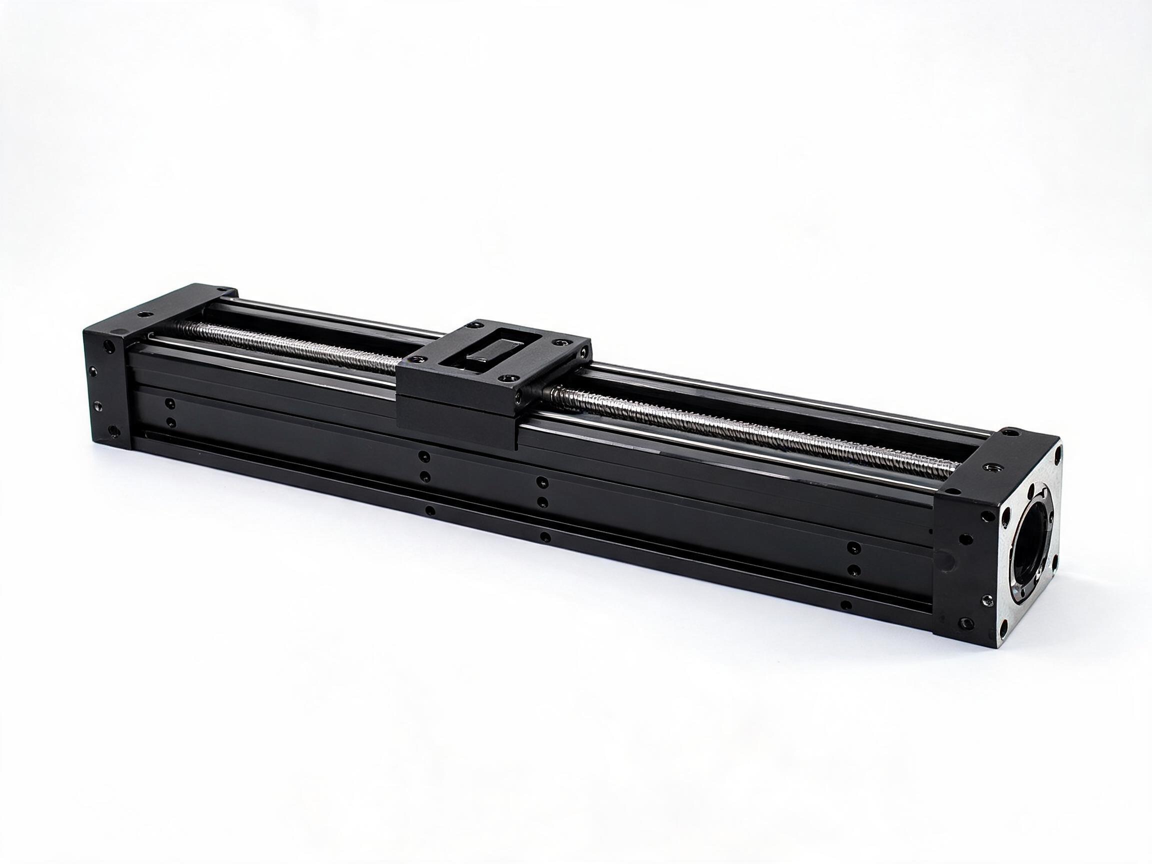
A selection comparison for buyers who have an axis to move but are unsure whether they need a rod-type electric actuator, a profile linear module or a positioning stage. The article separates the three families, shows which questions actually decide the choice — drive type, stroke, load direction, mounting face and motor interface — and works through a real profile module built from an HGR15 rail, HGH15CA carriage and SFU1605 ball screw.
Three suppliers can quote the same axis and mean three different products. An electric actuator, a linear module and a positioning stage all produce motorized linear travel, but they are built differently, mounted differently and bought on different numbers. This comparison separates the three families, then shows which questions decide the choice.
Selection comparisonThree families, one job: moving an axis with a motor
Rod-type electric actuators, profile linear modules and positioning stages all convert motor rotation into controlled linear movement. The similarity stops there. A rod-type actuator extends a threaded rod or lead screw out of a housing; a module carries a carriage along a rail inside an aluminium profile; a stage is a precision assembly usually supplied as a complete, calibrated positioning unit. Each family exists because some buyer needed a different envelope, mounting pattern or duty.
Because the names overlap in conversation, a quote can drift. Saying "linear actuator" to one supplier and "linear module" to another may return hardware that will not bolt into the same space. What removes the ambiguity is not a better family name — it is the numbers that go with it.
Characteristics of the three families
The table below compares what you can expect structurally and commercially. It contains no performance figures, because those come from the specific model you are quoted, not from the family name.
| Characteristic | Rod-type electric actuator | Profile linear module | Positioning stage |
|---|---|---|---|
| Typical structure | Housing with an extending rod or screw | Aluminium profile, linear rail, carriage, ball screw | Precision guideway and drive, often in a flat or box frame |
| Mounting style | Pivot or clevis points at both ends | Flat mounting face on the profile; carriage face carries the load | Baseplate or flange, usually with a defined reference datum |
| Space taken by travel | Retracted length plus stroke; rod extends beyond the housing | Envelope set by profile length; carriage travels along the rail | Envelope set by the stage frame and guide length |
| Typical drive | Lead screw or ball screw | Ball screw, lead screw or belt | Drive matched to the stage's positioning duty |
| Load direction | Mostly axial push and pull | Carriage load, often with a moment | Load applied to a defined moving face |
| What a quote usually centres on | Thrust, stroke, mount | Stroke, load, rail frame size, motor interface | Guide class, drive, travel and datum |
The honest point: a family name tells you nothing about performance. Stroke, load direction and drive decide whether a unit works in your machine. Two products both called "linear module" can differ by an order of magnitude in capability.
What actually decides the choice
Five questions carry most of the decision. Ask them before comparing price or brand.
- Drive type. Ball screw, lead screw and belt drives trade off differently. A screw type reacts to the stroke and load you need; a belt is chosen when the duty is different. The drive also determines how the motor connects, so it is settled early.
- Stroke. The distance the carriage or rod must travel, plus any overtravel and end-of-travel space. Stroke drives the length of the profile, screw and rail, which drives cost and stiffness.
- Load direction and magnitude. Whether the load pushes along the axis or hangs off the carriage changes the unit entirely. An axial pull is a different problem from a load applied at a distance from the carriage face.
- Mounting face and datum. How the unit bolts to your machine and how flat that surface must be. This is where a well-specified axis still fails to install.
- Motor interface. The motor, coupling and mounting flange. If your motor does not match the unit's mounting pattern, you need an adapter or a different motor — both have lead time.
Everything else — finish, profile size, cable routing — can be settled once these five are fixed.
How stroke and load are checked
Stroke and load are read together, not separately. A profile module with a 100 mm stroke and a long one with the same carriage are not interchangeable, and the load rating of a given unit applies to the way the load is applied.
Consider one concrete example. The SKF20 aluminium profile linear motion slide module uses a 6063-T5 aluminium profile with 2020-series T-slot compatibility, an HGR15 rail with an HGH15CA carriage, and an SFU1605 C7 ball screw with a 5 mm lead. Stroke options are 100, 200, 300 and 500 mm, with customisation up to 1000 mm. Its published dynamic load is 11.2 kN and static load 17.5 kN; the 500 mm version weighs 2.8 kg. The minimum order is 30 pieces.
Read that specification the way a buyer should: the 5 mm lead ball screw means one motor revolution moves the carriage 5 mm, so the motor, drive and required resolution are a calculation, not a guess. The dynamic and static load figures describe the unit, but they do not describe your carriage load at your stroke and speed. If your load is applied off-centre, calculate the moment and confirm with the supplier before ordering.
Mounting face and motor interface
These two items cause more first-article rejections than the drive selection. The SKF20 module requires the mounting surface to be parallel within 0.02 mm. That is a property of the installation, not of the module — if the machine base is not parallel to that tolerance, the profile will be stressed even though the module is within specification. Check how you will shim, machine or fixture the base before you fix the module design.
On the motor side, the SKF20 accepts NEMA 17 and NEMA 23 motor mounting. Confirm the motor frame, shaft diameter, and whether a coupling and motor mount are supplied with the module or provided by you. Specify the motor at the quotation stage, because the adapter or flange is part of the delivered configuration.
What to send in a selection request
A supplier can only select correctly if the request carries the numbers below. This is the same list a manufacturer needs to return a buildable quotation.
- Required stroke, and the total travel envelope including overtravel.
- Load mass and direction — axial, hanging, or offset from the carriage.
- Mounting orientation (horizontal, vertical, inclined) and how the unit will be fixed.
- Parallelism or flatness tolerance of the mounting surface.
- Motor frame size, shaft and whether the motor is supplied or buyer-supplied.
- Quantity, and the delivery term — EXW, FOB, DAP or DDP — so freight and duty are in the comparison.
- Any environmental condition that affects the drive or rail.
With those answers, three suppliers will quote comparable hardware. Without them, you may be comparing a rod actuator against a module against a stage and calling it a price difference.
FAQ
- What is a linear actuator?
- In general use, a linear actuator is any device that converts motor rotation into straight-line movement. That broad meaning covers rod-type actuators, profile modules and positioning stages — which is why the term alone cannot select hardware. For a full definition of the electric actuator type specifically, see our separate topic article.
- What is a linear module?
- A linear module is a linear motion unit built around an aluminium profile: a rail and carriage inside or on the profile, driven by a screw or belt. The SKF20 is one example, combining a 6063-T5 profile, an HGR15 rail with HGH15CA carriage and an SFU1605 ball screw.
- What is a linear stage?
- A linear stage is a precision positioning assembly, usually with a defined base datum and a moving face. It is chosen when the mounting geometry and guide precision, not the profile frame, are the dominating requirement.
- What is linear actuator stroke?
- Stroke is the distance the moving element travels, measured between its end positions. On the SKF20, standard stroke options are 100, 200, 300 and 500 mm; customised lengths go up to 1000 mm. The stroke you specify sets the length of the profile, rail and screw.
- How to select a linear actuator or module?
- Work through drive type, stroke, load direction, mounting face and motor interface, in that order. The family name is chosen after these are known, not before. If an off-centre load or a tight parallelism requirement is involved, confirm with the supplier rather than selecting from a catalogue.
- What is an electric linear actuator?
- An electric linear actuator is a linear motion device driven by an electric motor rather than hydraulics or pneumatics. It may be a rod type, a profile module or a stage; the electric drive is the common feature, not the structure.
- How much do linear actuators cost?
- Cost is a function of stroke, load and drive. A longer stroke needs a longer profile, rail and screw; a higher load needs a larger frame or a different carriage; the drive type changes the screw, belt and motor interface. Environmental conditions and quantity also move the number. Because these variables interact, a figure quoted for one configuration does not transfer to another — request a quotation against your stroke, load and motor details.
Next step
Send the stroke, load direction, mounting tolerance, motor frame and quantity, and a supplier can return a configured quotation with the drive and carriage matched to those inputs. If your requirement fits the SKF20 family, review the module specification and then raise a request for quotation with your axis data attached. The family name is only the start of the selection; the numbers are the decision.