
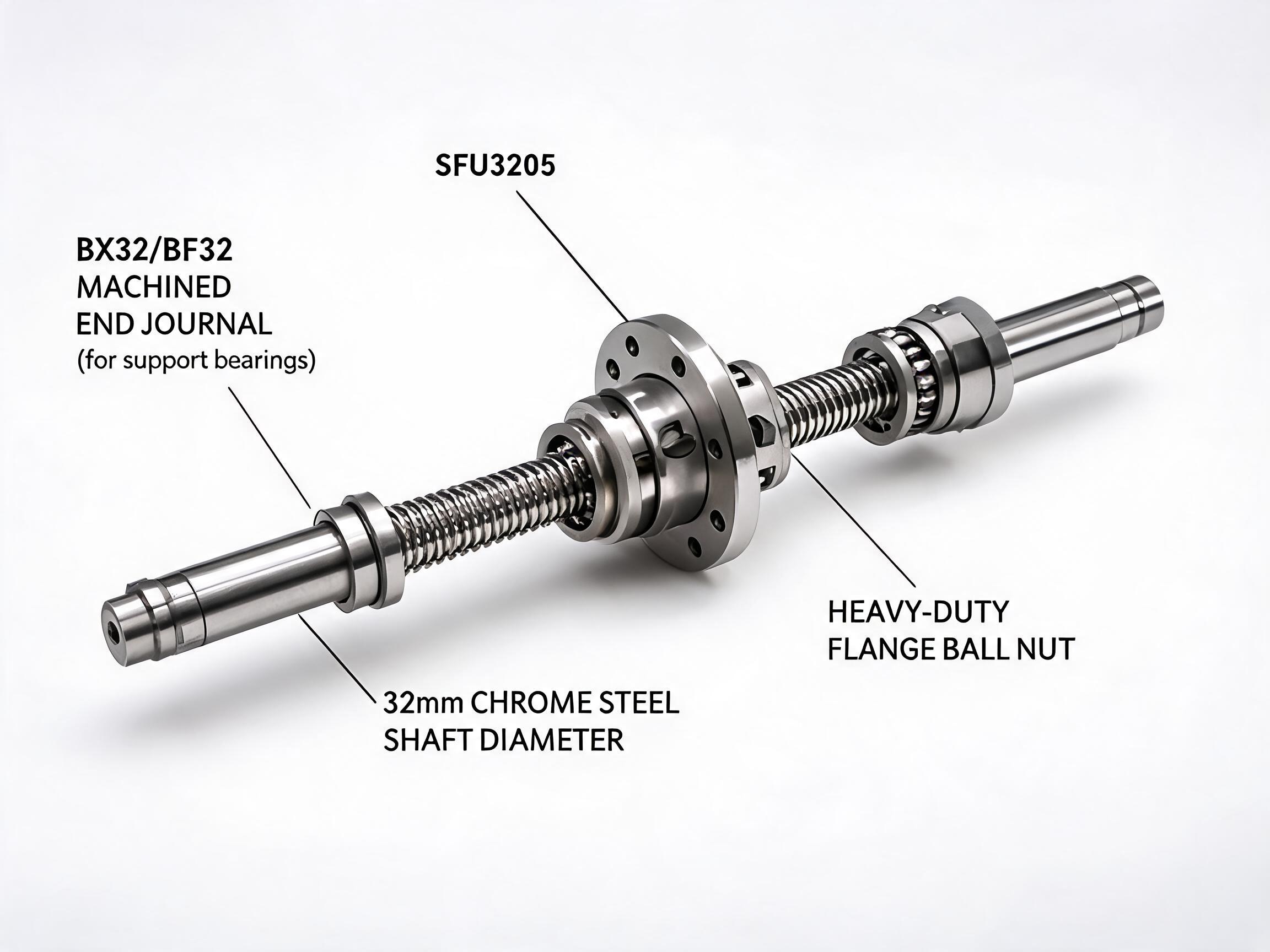
A practical engineering guide for buyers and design engineers on how to size a ball and screw linear actuator correctly. Covers thrust force calculation, speed and lead selection, duty cycle, critical speed, buckling load, and common sizing mistakes — with formulas and a worked example you can apply directly to your application.
ENGINEERING BUYER GUIDE
A ball and screw linear actuator converts rotary motor motion into precise linear movement. It is the workhorse of industrial automation — found in CNC machinery, packaging lines, material handling, medical equipment, and any application where repeatable positioning matters.
But sizing one is not a "pick the biggest one" exercise. Choose a screw actuator too small and it stalls under load. Choose too large and you pay for capacity you never use. The difference between a reliable machine and a recurring maintenance problem is usually decided in the first hour of calculation.
This guide walks through the four numbers that matter most — thrust force, required motor torque, screw lead, and speed — with the formulas and a worked example you can apply directly.
- Thrust force is the starting point — calculate the worst-case load, not the average.
- Screw lead determines the speed–resolution trade-off: higher lead = faster but coarser positioning.
- Motor torque must cover thrust plus friction plus acceleration, with a safety factor.
- Critical speed and buckling limit how fast and how long a screw can run.
- Duty cycle and service factor are often the difference between a 1-year and a 10-year actuator life.
1. Start with the Application Profile
Before any formula, define the operating envelope. A screw actuator is sized for the worst case, not the typical cycle. Collect these inputs first:
- Moving mass (kg) — the payload plus the carriage and any attached tooling.
- External force (N) — cutting force, clamping force, or pushing force applied by the actuator.
- Friction coefficient (μ) — of the guide rails or slide, typically 0.01–0.05 for linear guides, higher for plain slides.
- Stroke length (mm) — the full travel distance required.
- Required speed (mm/s or m/min) — maximum linear velocity during the cycle.
- Acceleration time (s) — how quickly the load must reach full speed.
- Duty cycle (%) — what percentage of the cycle time the actuator is actually moving.
Missing data is common. If you are early in the design phase, state your assumptions and confirm them with the actuator supplier — most reputable manufacturers will re-check your sizing before quoting.
2. Thrust Force Calculation
The total axial force the screw must deliver is the sum of all resistive forces:
| Force Component | Formula | Notes |
|---|---|---|
| Friction force | Ff = μ × m × g | g = 9.81 m/s² |
| Acceleration force | Fa = m × a | a = v / tacc |
| External load | Fext | Cutting, clamping, pushing force |
| Total thrust | F = Ff • Fa • Fext | Use worst-case values |
For vertical applications, add the weight of the moving mass (m × g) to the total. For horizontal applications, the weight acts on the guides, not the screw — but it still creates friction.
A common mistake is sizing for steady-state speed only. The acceleration force can be several times the friction force on short-stroke, high-cycle applications. Always calculate the thrust at the most demanding point of the cycle — usually at the start of motion or at the point of maximum external load.
3. Screw Lead and Speed Relationship
The screw lead (L) — the linear travel per revolution — is the single most important geometric parameter. It links speed and resolution:
| Parameter | Formula | Unit |
|---|---|---|
| Required screw speed | n = v / L | rev/s or rpm |
| Linear speed | v = n × L | mm/s |
| Resolution (with stepper) | Δx = L / (steps per rev) | mm/step |
Where:
- n = screw rotational speed (rpm)
- v = linear speed (mm/s)
- L = screw lead (mm/rev)
The trade-off is direct: a 5 mm lead gives fine resolution and high thrust per unit torque but requires high screw speed for fast linear motion. A 20 mm lead moves faster per revolution but needs more motor torque and gives coarser positioning.
For a target linear speed of 500 mm/s:
- 5 mm lead → 6,000 rpm (often too fast for standard ball screws)
- 10 mm lead → 3,000 rpm (typical maximum for rolled ball screws)
- 20 mm lead → 1,500 rpm (comfortable for most servos)
This is why lead selection is usually a compromise between speed, resolution, and torque — not a single-variable decision.
4. Required Motor Torque
Once the thrust is known, convert it to the torque the motor must deliver at the screw:
| Parameter | Formula | Unit |
|---|---|---|
| Torque from thrust | T = (F × L) / (2π × η) | N·m |
| Total torque | Ttotal = T + Tfriction • Taccel | N·m |
| With safety factor | Tmotor = Ttotal × SF | SF = 1.5–2.0 |
Where:
- F = total thrust (N)
- L = screw lead (m — convert from mm)
- η = efficiency (0.85–0.95 for ball screws, 0.30–0.50 for acme/lead screws)
- SF = safety factor
Note the efficiency difference. A ball screw at 90% efficiency converts nearly all input torque into thrust. An acme lead screw at 40% efficiency needs more than double the torque for the same load. This is the primary reason ball and screw linear actuators are specified over plain lead screws in high-duty applications — the energy savings and smaller motor requirement usually justify the higher screw cost.
The efficiency term is where ball screws win. At 90% vs 40% efficiency, the same thrust requires less than half the motor torque — which means a smaller motor, less heat, and lower energy consumption over the machine's life.
5. Critical Speed and Buckling Limits
Two mechanical limits constrain the screw itself, regardless of motor power.
Critical Speed
Every screw has a rotational speed above which it begins to whip or vibrate — the critical speed. It depends on the screw diameter, length, and end bearing support:
ncrit ≈ (K × d) / L²
Where:
- K = constant based on end fixity (typically 0.8–1.2 × 10⁶ for steel, varies with support)
- d = screw root diameter (mm)
- L = unsupported length (mm)
Rule of thumb: keep operating speed below 80% of critical speed. For long strokes, this often forces a larger screw diameter or a shorter unsupported span (adding a support bearing).
Buckling (Column Loading)
Under compression, a long slender screw can buckle before it reaches its thrust limit. The allowable compressive load decreases with the square of the unsupported length. For strokes above roughly 1,000 mm, buckling is frequently the limiting factor — not motor torque.
Both limits are why suppliers ask for stroke length and end support type before recommending a model. A screw that works at 500 mm stroke may be unusable at 1,500 mm without a diameter increase.
6. Worked Example — Sizing a Screw Actuator
Let's apply this to a typical horizontal positioning application:
| Input | Value |
|---|---|
| Moving mass (m) | 150 kg |
| Friction coefficient (μ) | 0.02 (linear guides) |
| External force (Fext) | 0 N (no cutting) |
| Required speed (v) | 300 mm/s |
| Acceleration time | 0.3 s |
| Stroke | 800 mm |
| Duty cycle | 60% |
Step 1 — Friction force:
Ff = 0.02 × 150 × 9.81 = 29.4 N
Step 2 — Acceleration force:
a = 0.3 / 0.3 = 1.0 m/s²
Fa = 150 × 1.0 = 150 N
Step 3 — Total thrust:
F = 29.4 + 150 + 0 = 179.4 N
Step 4 — Select lead and check speed:
Try a 10 mm lead. Required screw speed:
n = 300 / 10 = 30 rev/s = 1,800 rpm — acceptable for a rolled ball screw.
Step 5 — Motor torque:
T = (179.4 × 0.010) / (2π × 0.90) = 0.317 N·m
With a 1.8 safety factor: Tmotor ≈ 0.57 N·m
Step 6 — Check critical speed and buckling:
For an 800 mm stroke, a 20 mm diameter screw is typically sufficient. Confirm the critical speed for the actual unsupported length with the supplier — this is where a standard catalog model is usually verified against your specific stroke.
Result: a 20 mm diameter, 10 mm lead ball screw actuator with a servo or stepper motor rated above 0.6 N·m continuous torque.
7. Common Sizing Mistakes
| Mistake | Consequence | Fix |
|---|---|---|
| Sizing for average load, not peak | Motor stalls or overheats | Use worst-case thrust |
| Ignoring acceleration force | Undersized motor on short strokes | Always add Fa |
| Selecting lead for speed only | Poor resolution or excessive torque | Balance lead vs. speed vs. resolution |
| Overlooking critical speed on long strokes | Vibration, noise, premature wear | Increase diameter or add support |
| Using acme efficiency for ball screw calc | Oversized motor, wasted cost | Use η = 0.85–0.95 for ball screws |
| No safety factor on torque | Failure under voltage dips or load spikes | Apply SF = 1.5–2.0 |
8. When to Ask the Supplier
Even with a complete calculation, some values are best confirmed by the actuator manufacturer:
- Critical speed for your exact unsupported length and end fixity — catalog values assume ideal support.
- Dynamic load rating (C) and expected life in cycles — this is a fatigue calculation based on your load and travel per cycle.
- Backlash — for positioning accuracy, confirm the standard backlash class and whether preloading is needed.
- Lubrication and maintenance interval — depends on speed, load, and duty cycle.
- Environmental factors — dust, washdown, or temperature extremes change seal and lubricant selection.
A good supplier will re-run your numbers and flag anything that looks marginal. If they don't ask about your duty cycle or stroke, treat that as a warning sign.
9. Ball Screw vs. Lead Screw — A Quick Decision Guide
| Criterion | Ball Screw | Lead Screw (Acme) |
|---|---|---|
| Efficiency | 85–95% | 30–50% |
| Backlash | Low, can be preloaded | Higher, nut wear increases it |
| Speed capability | High | Limited by heat generation |
| Cost | Higher | Lower |
| Self-locking | No (can back-drive) | Often yes (holds position without brake) |
| Best for | High duty, precision, fast cycles | Low cost, low speed, vertical holding |
If your application runs continuously, needs precise positioning, or has a long stroke — a ball and screw linear actuator is usually the right choice. If the cycle is slow, infrequent, or the budget is tight, a lead screw may be sufficient.
Final Thoughts
Sizing a screw actuator is a five-step process: define the worst-case load, calculate thrust, select the lead, convert to motor torque, and verify the mechanical limits of the screw itself. None of these steps is difficult on its own — the risk is skipping one.
If you are early in a project and need help verifying your calculations, send the supplier your moving mass, stroke, required speed, and duty cycle. Most actuator manufacturers will provide a sizing recommendation based on those four inputs — and it costs nothing to ask.
Need help selecting a ball and screw linear actuator for your application? Contact our engineering team with your load, stroke, and speed requirements — we will confirm the sizing and recommend a suitable model.