
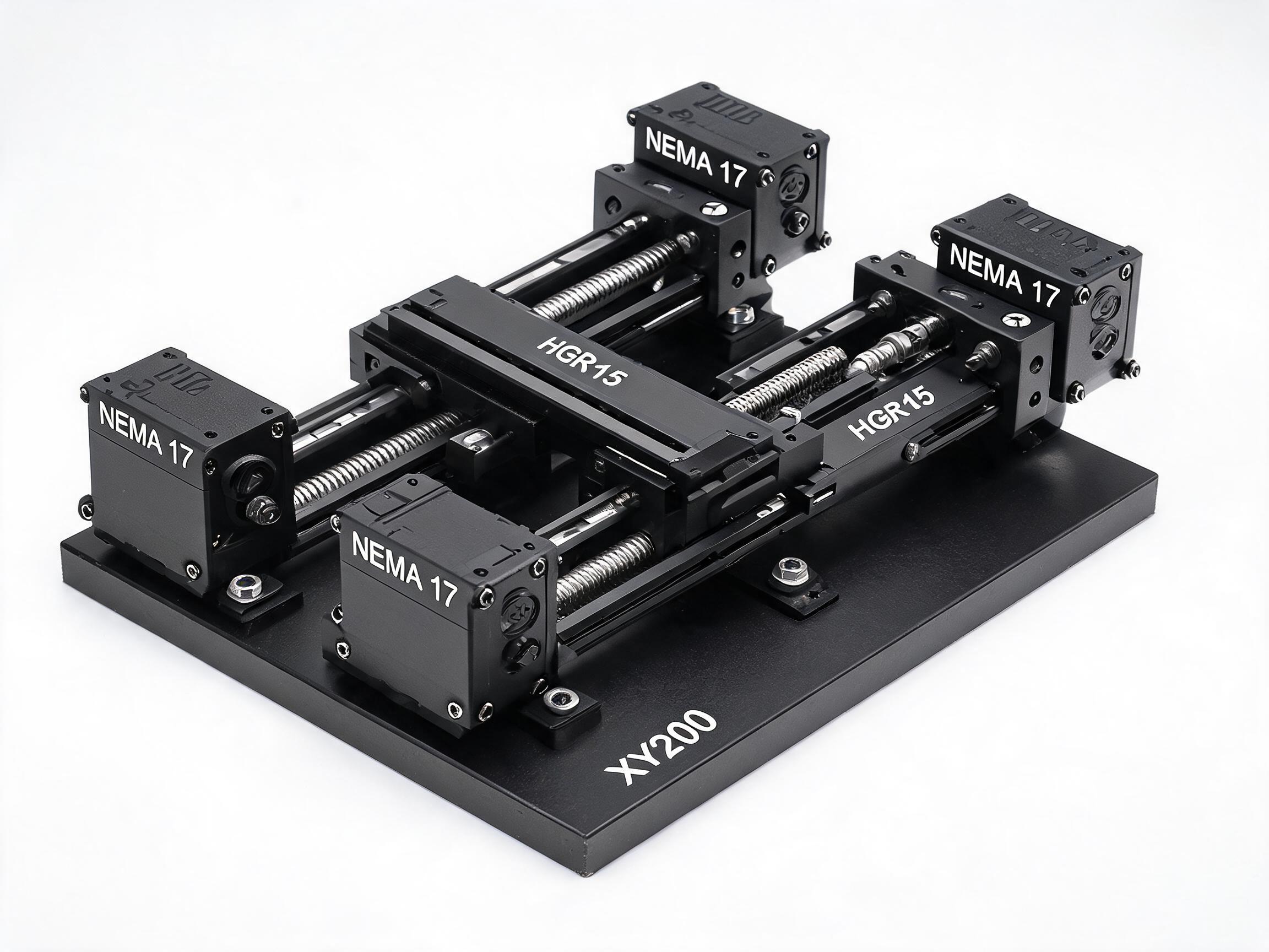
A buying decision guide for the ball screw linear actuator assembly question: what self-building an actuator really involves, where tolerance stack-up and alignment risk sit, and what a pre-integrated module already contains. Compared under the same conditions with our SKF20 module, XY200 cross table and SFU rolled screw series, with listed figures and MOQ.
The question behind a ball screw linear actuator assembly project is simple: buy one integrated unit, or buy a screw, rails, a carriage, a motor mount and machined parts and build it yourself. Both routes can end at the same working motion. They differ in who owns the tolerance stack-up, who debugs the alignment, and where the time goes before the first good part comes off the machine.
On this page
- What self-assembly actually involves
- The risks that sit inside a self-built actuator
- What a pre-integrated module already contains
- Same-conditions comparison with our products
- When each route wins
What self-assembly actually involves
A ball screw actuator is not one part. It is a chain of parts whose positioning errors combine. If you assemble it yourself, you are buying and joining at least the following:
- The screw and its support. A rolled screw such as our SFU series rolled ball screw assembly, listed at C7, ±0.05 mm per 300 mm, in 300 to 1500 mm lengths, HRC 58-62, MOQ 50. Lead accuracy and end support (fixed or floating bearing blocks) both enter the stack-up.
- The linear guide. Rail and carriage, chosen and mounted separately. Rail straightness, carriage preload and the mounting surface beneath the rail all affect final straightness of travel.
- The carriage or table top. The plate that carries the load. It must accept both the screw nut and the guide carriage, and its own machining sets where the load actually sits.
- The motor mount. Motor bracket, coupling, and the coaxial relation between motor shaft and screw end. Coupling misalignment loads both the motor bearing and the screw support.
- Machining and tolerance stack-up. Bearing seat diameters, shoulder squareness, screw end runout, mounting-hole patterns on the base plate. Each part is made to its own drawing; the assembly is only as good as the sum of those drawings.
The engineering work is real, and much of it happens before any part is cut: you must define the datum scheme, decide which faces are machined together, and write the assembly sequence so alignment is set by geometry rather than by a technician nudging parts into place.
The risks that sit inside a self-built actuator
Alignment and perpendicularity
Two errors dominate a first build. The first is screw-to-rail parallelism: if the screw axis and the rail are not parallel, the carriage binds over part of the stroke and runs free over another. The second is perpendicularity between the motor axis and the screw axis, which transfers into coupling wear and into position error that changes with direction of travel. Neither shows up on a part drawing. Both appear the moment the unit is powered and moved.
Where the design requires a stated squareness, ask the supplier to name the inspection method, not only the value. Our XY200 precision cross slide table with dual ball screw drive lists perpendicularity 90° ±0.02°, verified by CMM, with flatness ≤0.01 mm and repeatability ±0.01 mm, MOQ 20. Those values describe a measured condition under a stated method, which is what a self-built unit must reproduce from scratch.
Debugging time
A self-built unit spends its early life in debugging: checking rail straightness after mounting, checking screw runout after coupling, re-shimming the motor mount, re-running the stroke. Each check can send you back to a machined part. Budget this time as part of the project, not as an afterthought, and plan the checks in the sequence that finds the largest error first.
Responsibility split
When a fault appears, the screw supplier, the rail supplier and the machine shop can each show a part within its own specification. The assembly is out of tolerance anyway. Owning the integration means owning that argument as well.
What a pre-integrated module already contains
A pre-integrated module arrives as a matched set. Our SKF20 aluminum profile slide module is built on an aluminum profile base with an HGR15 rail and HGH15CA carriage, an SFU1605 screw, a 2020 T-slot table, and a listed dynamic capacity of 11.2 kN. MOQ is 30.
The practical difference is not that the parts are better individually. It is that the relations between them — rail-to-base, screw-to-rail, table-to-carriage — were set during manufacture, and the buyer receives one unit to mount and run. Bolt patterns and profile geometry are fixed, so the machine frame can be designed around a known envelope rather than around a drawing you have yet to finish.
What a module does not remove is the interface to your machine. Base mounting flatness, the frame surface under the module, and the coupling to your motor still belong to you. Confirm the motor-mount dimensions and the base flatness requirement from the supplier datasheet before designing the frame.
Same-conditions comparison with our products
The comparison below holds the application constant: a single-axis linear motion with a ball screw drive, a guide rail and a carriage, driven by a motor through a coupling. Both columns assume the same stroke range, the same load, and the same mounting face quality on the machine frame. Accuracy figures are attributed to the specific model that lists them — they are not interchangeable between models.
| Condition (same on both sides) | Self-built from components | Pre-integrated module |
|---|---|---|
| Screw supply | SFU rolled screw, C7 ±0.05 mm per 300 mm, 300 to 1500 mm, HRC 58-62, MOQ 50 | SFU1605 screw inside the SKF20 module |
| Guide supply | Rail and carriage sourced and mounted separately | HGR15 rail and HGH15CA carriage pre-mounted on the profile base |
| Table and carriage plate | Machined to your drawing; accepts nut and carriage | 2020 T-slot table included |
| Motor mount | Bracket, coupling and coaxial alignment built by you | Mounting interface defined by the module; motor coupling still yours |
| Screw-to-rail parallelism | Established at assembly and checked by you | Established during module manufacture |
| Perpendicularity evidence | Requires your own inspection plan | Listed on the XY200 cross slide table (a separate model in our range, not the SKF20): perpendicularity 90° ±0.02°, verified by CMM; flatness ≤0.01 mm; repeatability ±0.01 mm. The SKF20 module does not list these figures; confirm its accuracy per datasheet |
| Dynamic capacity reference | Depends on the selected rail and screw | 11.2 kN listed for the SKF20 module |
| Minimum order | SFU series MOQ 50 | SKF20 MOQ 30; XY200 MOQ 20 |
| Debugging owner | You | Interface to your machine only |
Read the table as a map of who owns what, not as a price comparison. Price depends on your quantities, the machining content of your parts and your inspection cost, none of which are fixed by the figures above. Ask for a quotation on the same stroke, load and mounting conditions on both routes before comparing totals.
When each route wins
Self-assembly tends to win when
- The actuator geometry is unusual — a stroke, envelope or mounting pattern that no listed module covers.
- You already have machining capacity and an inspection plan that can hold the stack-up.
- Volume is high enough that component purchasing and in-house assembly spread the engineering effort over many units.
- You need to control the sub-assembly design as part of a larger machine you are responsible for.
A pre-integrated module tends to win when
- The application fits a standard envelope and the accuracy figures listed for a specific module — for example, the XY200 cross table's CMM-verified values — are adequate for your requirement. For a module like the SKF20 that does not list repeatability, flatness or perpendicularity, confirm the accuracy with the supplier datasheet.
- Time to first good part matters more than the engineering freedom of a custom build.
- You want one supplier accountable for the screw-to-rail relation and the carriage fit.
- You need a stated inspection basis — CMM-verified perpendicularity on a model that lists it, such as the XY200 — rather than your own first-article inspection.
Key takeaways
- Self-assembly is an integration project: screw support, rail mounting, carriage plate, motor mount and a deliberate tolerance stack-up.
- The two largest risks are screw-to-rail parallelism and motor-to-screw perpendicularity; both appear only after the unit moves.
- A module fixes those relations during manufacture and leaves you the machine interface.
- Compare the two routes on the same stroke, load and mounting face, with quotations that include machining and inspection.
- For custom geometry or high volume with in-house machining, components can be the better route; for a standard envelope and a stated inspection basis, the module usually is. Check which accuracy figures the specific module actually lists — verified values such as the XY200's must not be read across to other models like the SKF20.
Figures quoted above are the listed values for the SKF20 module, the XY200 cross slide table and the SFU rolled screw series, each attributed to its own model. Confirm motor-mount dimensions, base flatness requirements, model-specific accuracy figures and current MOQ against the supplier datasheet for your specific order.