
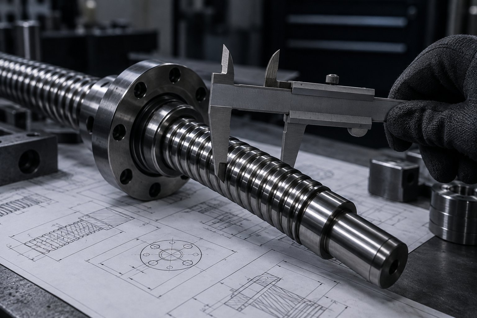
A decision-sequence guide for engineers and buyers specifying ball screw diameter. Learn which application inputs push the shaft diameter up, how to check load, unsupported length, critical speed, rigidity, and mounting configuration before requesting a quote, and what measurements to send a supplier for an accurate recommendation.
Ball screw diameter is not chosen in isolation, and it is rarely the first number you should fix. It falls out of a sequence of application inputs: the load the screw must move, the span it has to bridge without support, the speed it must reach, the rigidity the axis needs, and how the ends are mounted. Get the order wrong and you either over-order a heavy, expensive screw or under-size one that whips, deflects, or wears prematurely. This guide walks through that decision sequence so you can arrive at a diameter you can defend before you request a quote.
Key takeaways
- Diameter usually follows from unsupported length and speed first, then axial load and rigidity.
- Longer unsupported spans and higher speeds push diameter up because of critical speed and shaft whip.
- Mounting and support configuration can change the effective span more cheaply than increasing diameter.
- Lead, nut type, and preload interact with diameter; settle diameter and lead together.
- Send a supplier the application inputs listed at the end, not just a diameter guess.
What this guide covers
- The inputs that actually determine diameter
- Load and its effect on diameter
- Length, unsupported span, and critical speed
- Rigidity, accuracy, and mounting configuration
- A stepwise checking order
- The measurements to send your supplier
The inputs that determine diameter
When engineers ask how to select ball screw diameter, the honest answer is that several requirements set a minimum, and the largest minimum wins. The typical inputs are:
- Axial load: the force the screw must push or pull, including payload, friction, and any cutting or pressing forces.
- Length and unsupported span: the distance between bearing supports, which drives both buckling and critical speed limits.
- Speed: the maximum linear speed and the corresponding rotational speed, which interact with length to create whip risk.
- Required rigidity: how much axial deflection or positioning error the process can tolerate.
- Mounting and support configuration: fixed, supported, or free ends, and whether an intermediate support is possible.
- Environment and duty: contamination, lubrication, duty cycle, and target life, which influence surface hardness and material choices such as through-hardened or induction-hardened shafts in the 58–62 HRC range for wear resistance.
Load and its effect on diameter
Axial load sets a lower bound on diameter because a slender shaft can buckle under compression or deflect too far under thrust. The relationship is not linear: a modest increase in diameter raises the second moment of area sharply, so a small step up in diameter adds a disproportionate amount of stiffness.
In practice, load alone rarely dictates a large diameter in ordinary positioning axes. It becomes the deciding input in applications such as pressing, injection molding, or heavy vertical lifting, where thrust is high and continuous. Even then, you should check load together with span, because a heavily loaded short screw and a lightly loaded long screw can end up at similar diameters for different reasons.
When the load is compressive, also confirm the buckling condition with the supplier. The allowable compression load depends on end fixity, which is why mounting configuration matters as much as raw force.
Length, unsupported span, and critical speed
This is the pair of inputs that most often pushes diameter up, and it is the one buyers most often underestimate. A rotating screw that is too slender over a long span will develop a whirling vibration known as whip as it approaches its critical speed. The critical speed falls as the unsupported span increases, so a long axis either needs a larger diameter, a lower speed, or an intermediate support.
| What changes | Effect on required diameter | Practical response |
|---|---|---|
| Unsupported span increases | Pushes diameter up to keep critical speed above the operating speed | Add an intermediate support, or accept a larger screw |
| Required speed increases | Pushes diameter up for the same span | Reduce speed, increase diameter, or shorten the span |
| Both span and speed increase | Strongly pushes diameter up; can dominate all other inputs | Reconsider the axis architecture before ordering |
| Intermediate support added | Can reduce the diameter the rest of the design needs | Check whether the machine allows a support and its travel envelope |
A useful discipline is to establish the maximum rotational speed the drive and process genuinely require, then estimate the unsupported span. If the two together sit near the whip threshold for the candidate diameter, the diameter is not decided yet — you have a trade-off to resolve with your supplier, not a number to fix on your own.
Rigidity, accuracy, and mounting configuration
Axial rigidity depends on diameter, but also on nut preload, bearing support stiffness, and how the screw ends are fixed. A larger diameter adds stiffness, but it also adds inertia, which can slow acceleration and increase motor sizing. Buying extra diameter to gain rigidity can quietly cost you dynamic performance.
Mounting configuration is the lever buyers underuse. A screw supported at both ends, or fixed at one end and supported at the other, behaves very differently from one supported at a single end. Changing the support arrangement can raise critical speed and buckling resistance without changing the shaft diameter at all. This is often cheaper and lighter than stepping up a size.
A stepwise checking order
Rather than starting from a diameter and checking whether it works, work in this order. Each step can eliminate candidates or force a design change before you commit to a quote.
- Define the motion profile. Total stroke, maximum linear speed, acceleration, and duty cycle. These set the speed requirement that critical speed will act against.
- Measure or define the unsupported span. The distance between bearing supports, not the overall screw length. This is the single most important geometric input.
- Estimate the axial load including payload, friction, and process forces, and note whether it is compressive, tensile, or reversing.
- Check critical speed and buckling for a candidate diameter. If either limit is close to the operating point, change the support configuration or the span before increasing diameter.
- Check axial rigidity against the process tolerance. If the axis cannot hold position, consider nut preload and support stiffness alongside diameter.
- Confirm lead and nut type that fit the selected diameter and the required speed and resolution.
- Review environment and duty for material and surface hardness, lubrication, and sealing needs.
If the checks converge on a diameter that is far larger than you expected, the right move is usually to change the machine geometry — shorten the span or add a support — rather than to absorb a heavy, high-inertia screw into the axis.
What to send your supplier for an accurate recommendation
A supplier can size a ball screw much faster and more accurately if you send application inputs instead of a guessed diameter. Prepare the following:
- Motion profile: stroke length, maximum and typical linear speed, acceleration, and duty cycle.
- Geometry: overall screw length and the unsupported span between bearing supports, plus a sketch of the mounting arrangement.
- Load: axial load magnitude and direction, including peak and continuous values, and whether the load is compressive.
- Accuracy requirement: positioning tolerance or allowable axial deflection for the process.
- Environment: contamination, temperature range, lubrication access, and expected service life.
- Drive details: motor or gearbox constraints, coupling, and available envelope.
- Interface details: end machining requirements and how the nut will attach to the moving element.
With these inputs, a manufacturer can recommend a diameter, lead, nut type, preload, and support arrangement that fit the application rather than forcing the application to fit a stock size. Xiamen Dongfeng Bearing has manufactured linear motion components since 2014, including ball screws, linear guideways, linear bearings, and support units, with ISO 9001:2015 quality management, CE marking, and SGS material verification. Ball screws are produced with surface hardness in the 58–62 HRC range for wear resistance, and are backed by a 24-month warranty. OEM and ODM options are available for buyers who need application-specific end machining or configurations.
If you are still comparing options before a formal quote, send the inputs above for a sizing check first. A recommendation based on the real motion profile and span is more useful than a price for a diameter that may not run.