
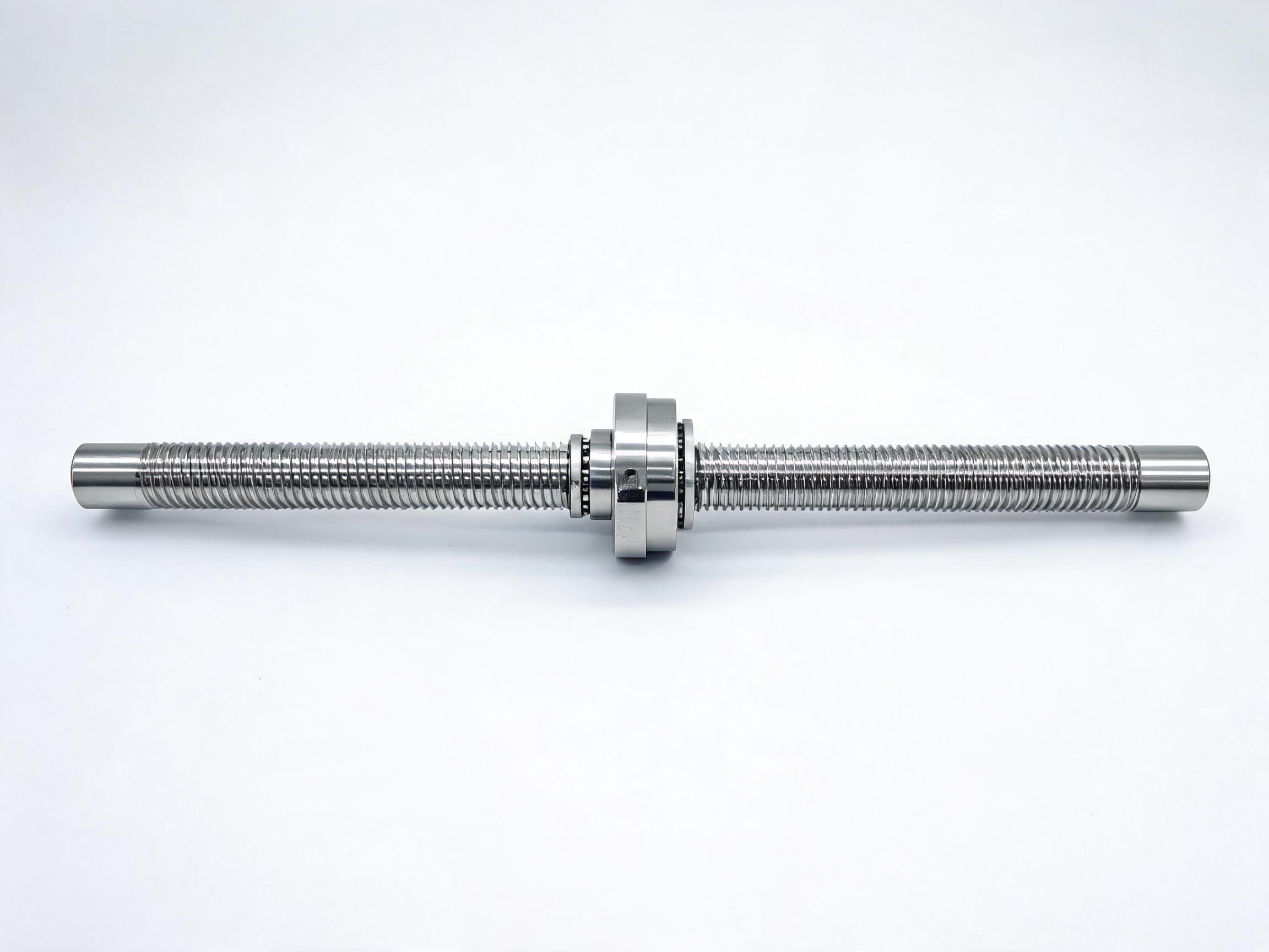
A stroke planning guide for long-travel axes built on standard rolled ball screw assemblies: catalogued length ranges by diameter, why end support choice matters more as the screw grows, qualitative screw whip and buckling limits, and what to confirm with the supplier before ordering.
Buyers specifying a long-travel axis usually start with a question about the screw: how far can a standard rolled ball screw travel before the design has to change? The answer depends on diameter first, on the end supports second, and on the accuracy class third. This guide stays at the planning level and uses catalogued long-length assemblies as reference points, not as a single-model walkthrough.
Key takeaways
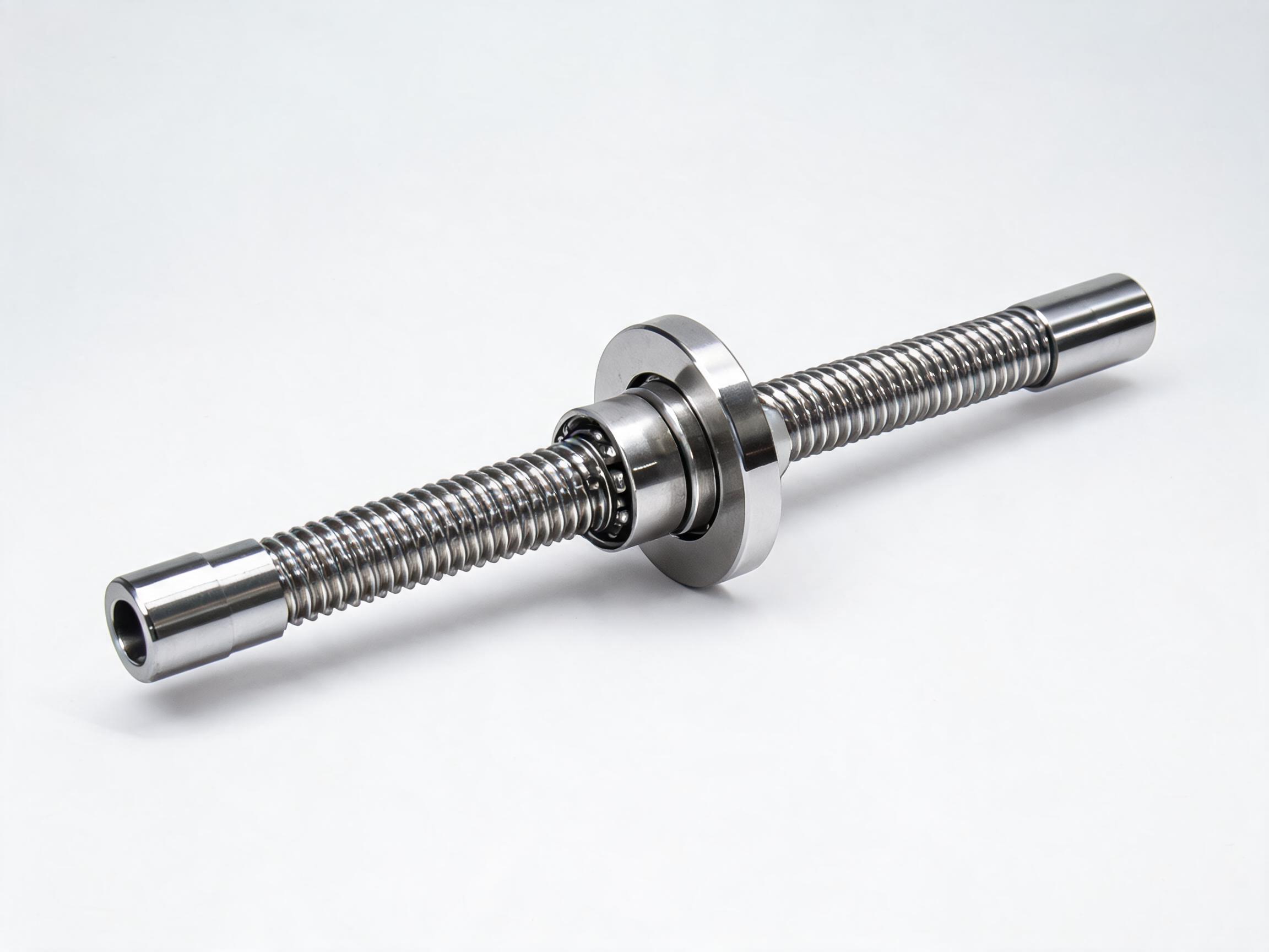
- Catalogued rolled ball screw assemblies reach different maximum lengths by diameter: the SFU1605 class is listed up to 1500 mm, SFU2510 up to 3000 mm, and SFU3205 up to 4000 mm.
- Longer screws are supported at both ends, and the bearing arrangement listed alongside the length (BK25/BF25 for SFU2510, BK32/BF32 for SFU3205) is part of the assembly, not an accessory.
- Screw whip and column buckling both worsen with unsupported length, so critical speed and load limits should be reviewed for every long-stroke axis.
- Accuracy grades apply over a defined length, so the tolerance you need at the far end of the travel has to be checked against the grade's basis.
- Long screws should be straightness-verified before installation; transport and handling can disturb a screw that was straight at the factory.
In this guide
- Catalogued length ranges by diameter
- End supports: why they matter more as the screw grows
- Screw whip and buckling in qualitative terms
- Accuracy grade over long travel
- Confirming a long-stroke order with the supplier
Catalogued length ranges by diameter
Standard rolled ball screw assemblies are catalogued in size families, and each family has a working length ceiling that reflects how the screw and its supports are built. The values below are catalogue listings for the named assemblies. Other diameters and other lengths sit in their own families and should be confirmed against the datasheet rather than inferred from these rows.
| Assembly family | Catalogued length | End supports listed | Catalogued accuracy |
|---|---|---|---|
| SFU1605 class | up to 1500 mm | confirm against the datasheet | confirm against the datasheet |
| SFU2510 | up to 3000 mm | BK25/BF25 | C7, 0.05 mm per 300 mm |
| SFU3205 | up to 4000 mm | BK32/BF32 | confirm against the datasheet |
The pattern in the table is straightforward: as the diameter grows, the catalogued length grows with it. That is not a marketing gradient but a structural one. A larger-diameter screw is stiffer for the same span, and the matching support pair is sized to carry it. The SFU2510 example is useful precisely because its full configuration is listed: 3000 mm length with BK25/BF25 supports, a dynamic load rating of 17.2 kN and a static rating of 26.5 kN, in C7 accuracy at 0.05 mm per 300 mm. For a longer axis still, SFU3205 reaches 4000 mm with BK32/BF32 supports and ratings of 22.5 kN dynamic and 34.8 kN static. If you are already working within these families, the product pages for the SFU series rolled ball screw assembly range are the place to compare the families side by side.
End supports: why they matter more as the screw grows
A short screw can be carried by relatively simple bearing blocks and still behave. A long screw cannot. Length changes the mechanics in two ways that both point back to the supports: the rotating mass and span make the shaft more sensitive to vibration, and the axial load path puts the screw in compression or tension depending on how it is preloaded.
The support pairs listed in the catalogue are fixed-floating arrangements. BK-type blocks are the fixed end: they locate the screw axially and take the thrust. BF-type blocks are the floating end: they allow the screw to accommodate thermal growth and minor misalignment along its length. In a long-stroke axis, this division of labour is what keeps the screw from being over-constrained. Both blocks are needed, and the correct pair is specified with the screw, not picked afterwards.
What changes when the span increases
- Thermal growth. A longer screw grows more in absolute terms when it warms up during operation, so the floating end has to absorb more travel.
- Misalignment amplification. A small angular error between the two ends of the axis produces a larger offset the further apart the supports are.
- Mounting stiffness. The rail or machine frame carrying the blocks has to hold the two ends in a consistent relationship; the screw cannot correct a frame that flexes.
- Handling sensitivity. A long screw is easier to bend in transit and during mounting, so installation procedure matters more, not less, at the top of the length range.
The SFU2510 nut as a reference
The nut does not solve a long-stroke problem on its own. A flange nut carries the load into the moving carriage, while the end supports determine whether the screw stays straight and stable while that carriage travels. Treating the supports as a separate purchase item is where long-stroke designs usually go wrong.
Screw whip and buckling in qualitative terms
Two limits dominate long-travel ball screw design, and both tighten as unsupported length grows.
Screw whip (critical speed)
Every rotating shaft has a speed at which its natural lateral vibration becomes self-reinforcing. For a ball screw, that speed falls as the span between supports increases and as the screw becomes more slender. Approaching it produces visible vibration, noise and accelerated wear at the supports and nut.
This is why long-travel axes often run lower rotational speeds for the same linear speed, and why larger diameters are used when the travel and the required speed both grow. The exact critical speed depends on the support arrangement, the screw geometry and the end-fixity conditions. A working formula exists, and your supplier should apply it to the proposed screw and supports. Any numeric check should be calculated for your specific design, not copied from a general article.
Column buckling
When the screw is in compression, the axial load can cause it to bow sideways. The longer the span, the lower the load at which this happens. Compression arises in certain drive and preload arrangements; a screw loaded mainly in tension is less exposed to buckling but may have different support requirements.
The same discipline applies: buckling capacity is calculated from the actual screw, the actual support fixity and the actual axial load. It should not be assumed from the dynamic load rating alone, which describes the ball track rather than the shaft as a column.
For a long-stroke axis, the useful question to put to the supplier is whether both limits have been checked for the proposed assembly at the intended travel, speed and axial load, and what the recommended operating envelope looks like.
Accuracy grade over long travel
Rolled ball screw accuracy grades describe the permissible error over a defined length, not over the whole screw. A C7 assembly quoted at 0.05 mm per 300 mm, as listed for SFU2510, expresses the tolerance basis in 300 mm increments. If your machine needs a particular positional tolerance at the far end of a long travel, that tolerance has to be evaluated against how the grade accumulates over the full length, not just one increment.
Two practical consequences follow:
- The end of the travel is not the same as the start. Positional error builds along the screw, so a design that is comfortably inside tolerance near the home position may be at the edge of it at the far end.
- Grade selection is a system decision. If the far-end error matters, a higher grade or a different diameter may be needed; the grade label alone does not settle it.
For a long-stroke axis, ask the supplier how the stated grade translates to the full travel length of the specific screw being quoted. That answer, rather than the per-300-mm figure by itself, is what your machine design has to live with.
Confirming a long-stroke order with the supplier
Long-length assemblies are usually quoted per project rather than stocked, so the request should carry enough detail for the supplier to check the limits rather than simply pick the longest catalogue row. The checklist below covers what to specify and what to verify back. It is deliberately short: these are the points that change the answer, not a general form.
| Item | What to state or ask |
|---|---|
| Travel and overall length | Required stroke, plus the screw length needed for nut travel and end supports. |
| Diameter and lead | The size family you are working in; whether a larger diameter is needed to meet speed or stiffness targets. |
| End supports | Confirm the fixed-floating pair that matches the screw, and how it is mounted on your frame. |
| Operating speed | Maximum rotational speed, so critical speed can be checked against the proposed span. |
| Axial load | Direction and magnitude of thrust, so buckling and support loading can be evaluated. |
| Accuracy grade | The tolerance you need at the far end of travel, and how the grade maps onto the full length. |
| Straightness verification | How straightness is checked and recorded before shipment, and how to re-check it on arrival and during installation. |
| Handling and installation | Support during transport, lifting method and mounting sequence for a long screw. |
Two of these items are worth highlighting because they are frequently under-specified. First, straightness verification: a long screw should be confirmed straight before it goes into the machine, and the supplier should say how that is done and what the acceptance basis is. Second, the accuracy mapping: the grade figure is a basis, not a guarantee of end-to-end tolerance, and the supplier should be able to explain how it applies to your travel length.
Where a long-travel axis needs a heavier-duty assembly, the SFU3205 heavy-duty rolled ball screw page shows the 4000 mm configuration with BK32/BF32 supports, and the SFU2510 rolled ball screw assembly with flange nut page documents the 3000 mm configuration in detail. Both are catalogue references for the planning questions above, not a substitute for a calculated check on your specific axis.
Planning sequence for a long-travel axis
- Fix the required stroke and the screw length that follows from it.
- Choose the diameter family whose catalogued length covers that length, moving up a family if the margin is thin.
- Confirm the fixed-floating support pair for that family and check that your frame can hold both ends consistently.
- Check critical speed and buckling against the intended speed and axial load, using your actual design inputs.
- Map the accuracy grade onto the full travel and decide whether the far-end tolerance is acceptable.
- Agree straightness verification and installation handling with the supplier before the order is placed.
The catalogue tells you which assemblies exist at which lengths. The supports, the calculated limits and the accuracy mapping tell you whether a given length will work in your machine. Both belong in the enquiry.