
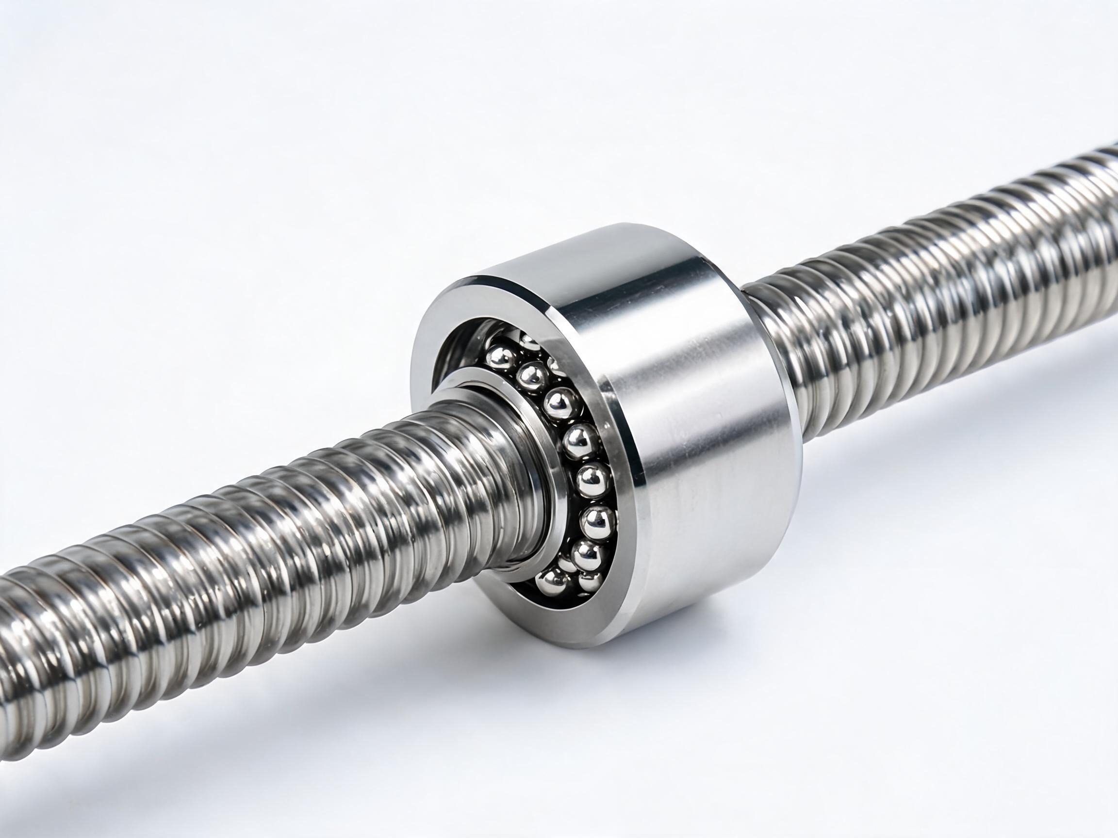
A practical guide for B2B buyers and engineers on ball screw selection. Covers accuracy grade differences (C5 vs C7), how to choose lead, preload methods (single nut vs double nut, oversize balls), and step-by-step load calculation with worked examples. Written for international procurement teams who need real numbers, not marketing fluff.
BALL SCREW BUYER GUIDE
Ball Screw Selection in Practice: C5 vs C7 Accuracy, Lead Choice, Preload Methods, and Load Calculation
Selecting a ball screw is rarely the most glamorous part of a machine build, but it is often the component that decides whether your axis holds position, wears evenly, and hits its cycle time. Get it wrong, and you chase backlash, vibration, or premature wear for the life of the machine.
This guide covers the four decisions that matter most in ball screw selection: accuracy grade (C5 vs C7), lead selection, preload method, and load calculation. Each section gives you concrete numbers and a decision framework, not general advice.
- C5 and C7 differ by about 3x in positional accuracy — C7 is fine for most material handling and general automation; C5 is required for machining, measuring, and precision positioning.
- Lead choice is a trade-off between speed and resolution. Doubling the lead doubles theoretical speed but halves the positioning resolution for the same encoder.
- Preload removes backlash but adds heat and reduces efficiency. Choose the lightest preload that meets your stiffness requirement.
- Always calculate the axial load at the worst-case position — usually at the end of stroke during acceleration or cutting. Use the dynamic load rating (Ca) for life calculation, not the static one.
1. Accuracy Grade: C5 vs C7 — What the Numbers Actually Mean
Ball screw accuracy grades are defined by JIS B1192 and ISO 3408-3. The grade letter (C0, C1, C3, C5, C7, C10) refers to the maximum deviation of travel per 300 mm of screw length.
| Grade | Positioning Accuracy per 300 mm | Typical Application |
|---|---|---|
| C0 | 3.5 µm | Ultra-precision machines, semiconductor equipment |
| C1 | 5 µm | High-precision machining centers |
| C3 | 8 µm | Precision grinding, EDM, high-end CNC |
| C5 | 18 µm | Standard CNC, precision automation, measuring equipment |
| C7 | 50 µm | General automation, material handling, simple positioning |
| C10 | 210 µm | Rough positioning, manual feed, low-cost systems |
Key fact
The difference between C5 and C7 is roughly a factor of 2.8 in positional deviation. That is significant, but it is not the whole story.What C5 Gives You Beyond Accuracy
- Tighter lead error control — C5 screws have a more consistent lead over the full travel, which matters for synchronized axes or threading operations.
- Better repeatability — less variation between passes to the same position.
- Higher cost, typically 30–60% more than C7 for the same size and length, depending on grinding vs rolling manufacturing method.
When C7 Is the Right Choice
If your application is:
- Conveyor positioning
- Pick-and-place with mechanical stops
- Simple linear transfer with position tolerance above ±0.05 mm
- Vertical lifting with gravity assist
...then C7 is the cost-effective choice. A C7 rolled ball screw is also generally faster to manufacture, which means shorter lead times.
When You Must Choose C5
- CNC machining (even light-duty)
- Laser cutting or marking with precision registration
- Measurement and inspection stages
- Any axis where the encoder resolution is below 5 µm and you rely on the screw for final positioning
2. Lead Selection: Speed vs Resolution
The lead (also called pitch) is the linear travel per one revolution of the screw. It is the most consequential dimension you will choose, because it sets the relationship between motor speed and linear velocity.
The Core Trade-off
- Large lead (e.g., 20 mm or 40 mm) → higher linear speed for the same motor RPM, but lower positioning resolution (each motor step or encoder count moves the axis further).
- Small lead (e.g., 5 mm or 10 mm) → higher resolution and better holding stiffness, but you need higher motor RPM for the same speed.
How to Calculate Required Lead
The basic formula:
Required lead (mm) = Maximum linear speed (mm/min) ÷ Motor rated speed (RPM)
Example: You need 30 m/min (30,000 mm/min) and your servo motor is rated at 3,000 RPM.
Lead = 30,000 ÷ 3,000 = 10 mm
Now check the resolution:
If your motor encoder is 2,500 pulses/rev (typical incremental encoder), and you use a 1:1 coupling:
Resolution = 10 mm ÷ 2,500 = 4 µm per pulse
That is acceptable for most automation. If you need 1 µm resolution, you would need a 10,000-line encoder or a smaller lead (2.5 mm) — which would cap your speed at 7.5 m/min at 3,000 RPM.
Practical Lead Selection Guide
| Application Type | Typical Lead Range | Notes |
|---|---|---|
| Precision grinding / EDM | 5–10 mm | Resolution priority; speed is secondary |
| CNC milling / turning | 10–20 mm | Balance of speed and rigidity |
| General automation / pick-and-place | 10–20 mm | Speed matters; resolution from encoder |
| High-speed transfer (>30 m/min) | 20–40 mm | Large lead; check critical speed first |
| Vertical axes | 5–10 mm | Smaller lead gives better holding torque; consider brake |
Critical speed check
For long screws, the critical speed (where the screw starts to whip) often limits you before the motor does. For a 1-meter unsupported length, a 25 mm diameter screw has a critical speed around 1,200–1,500 RPM depending on end fixity. Always verify this before finalizing the lead.3. Preload Methods: Which One and How Much
Preload removes the axial clearance (backlash) between the nut and screw shaft. Without preload, a ball screw has 0.02–0.10 mm of play, which is unacceptable for any bidirectional positioning.
The Three Common Preload Methods
| Method | How It Works | Preload Amount | Best For |
|---|---|---|---|
| Oversize balls | Ball diameter is 2–5 µm larger than standard; assembled under pressure | Light (3–8% of dynamic load) | General automation, cost-sensitive applications |
| Single nut with lead shift | Nut has two circuits with a slight lead difference; creates internal axial force | Light to medium (5–10%) | Standard positioning, where compactness matters |
| Double nut | Two nuts separated by a spacer or shim; tightened axially to create preload | Medium to heavy (10–15%) | CNC machining, high-stiffness requirements |
How Preload Affects Performance
- More preload = higher stiffness (less deflection under load) but also higher friction torque, more heat generation, and lower efficiency.
- Heat is the hidden enemy. A heavily preloaded nut can run 10–20°C hotter than a lightly preloaded one. Thermal growth of the screw shaft directly causes positional error — which defeats the purpose of buying a C5 screw.
- Efficiency drops from ~90% (no preload) to ~75–80% with heavy preload. That means more motor torque required and more heat.
Selection Rule of Thumb
- Light preload (oversize balls): Use for horizontal axes with moderate load, where backlash removal is needed but stiffness demand is modest.
- Medium preload (lead shift or light double nut): Standard choice for CNC and precision automation.
- Heavy preload (double nut, 10–15%): Only for vertical axes, high-cutting-force applications, or where the axis must hold position under interrupted loads.
4. Load Calculation: The Step-by-Step Method
The load on a ball screw is not constant. It varies with acceleration, cutting force, gravity (for vertical axes), and friction. You must calculate the equivalent dynamic load — the constant load that would produce the same fatigue life as your actual variable load profile.
Step 1: Calculate Axial Load for Each Phase of the Cycle
For a horizontal axis, the axial load during motion is:
F = μ × m × g + Fcut • m × a
Where:
- μ = friction coefficient of guide rails (typically 0.01–0.05 for linear guides)
- m = moving mass (kg)
- g = 9.81 m/s²
- Fcut = cutting or process force (N), if any
- a = acceleration (m/s²)
For a vertical axis, add the weight:
F = m × g + m × a + Fcut (during upward acceleration)
Step 2: Calculate Equivalent Dynamic Load (Fm)
For a cycle with multiple phases (accelerate, constant speed, decelerate, dwell), use:
Fm = ∛[(F₁³ × t₁ + F₂³ × t₂ + ... + Fₙ³ × tₙ) ÷ (t₁ + t₂ + ... + tₙ)]
This is the cube-root mean, because ball screw fatigue life follows a cubic relationship with load.
Step 3: Calculate Rated Life
L = (Ca ÷ Fm)³ × 10⁶ (revolutions)
Convert to hours:
Lh = L ÷ (60 × navg)
Where navg is the average screw speed in RPM.
Worked Example
Given:
- Moving mass: 200 kg
- Guide friction coefficient: 0.02
- Maximum speed: 20 m/min
- Acceleration time: 0.2 s (accel and decel)
- Constant speed time: 1.0 s
- Dwell time: 0.5 s
- Lead: 10 mm
- No cutting force
Step 1 — Forces:
- Friction: Ff = 0.02 × 200 × 9.81 = 39.2 N
- Acceleration: a = (20 m/min ÷ 60) ÷ 0.2 s = 1.67 m/s²
- Inertia force: Fa = 200 × 1.67 = 333 N
- During accel: F₁ = 39.2 + 333 = 372 N
- During constant speed: F₂ = 39.2 N
- During decel: F₃ = 39.2 − 333 = −294 N (use absolute value: 294 N)
- During dwell: F₄ = 0 N (no motion)
Step 2 — Equivalent load:
Fm = ∛[(372³ × 0.2 + 39.2³ × 1.0 + 294³ × 0.2 + 0³ × 0.5) ÷ (0.2 + 1.0 + 0.2 + 0.5)]
Fm = ∛[(10.3M + 60K + 5.1M) ÷ 1.9] ≈ ∛(8.1M) ≈ 201 N
Step 3 — Life:
With a 25 mm diameter screw, Ca ≈ 12,000 N (typical for this size):
L = (12,000 ÷ 201)³ × 10⁶ = 59.7³ × 10⁶ ≈ 2.13 × 10⁸ revolutions
Average speed = (20 m/min ÷ 0.01 m) × (1.4/1.9 duty) ≈ 1,474 RPM
Lh = 2.13 × 10⁸ ÷ (60 × 1,474) ≈ 2,400 hours
That is low for a production machine — most buyers target 20,000+ hours. You would need a larger screw (higher Ca) or a lower load profile.
5. Putting It Together: A Selection Checklist
Before you send an RFQ, have these numbers ready:
- Accuracy grade — C5 or C7, based on your positioning tolerance and the rest of the system's accuracy.
- Lead — calculated from speed and resolution requirements; verify critical speed for long screws.
- Preload method — oversize balls for light duty, double nut for high stiffness; specify preload as a percentage of Ca.
- Load and life — equivalent dynamic load (Fm) and required life in hours; then select a screw with adequate Ca.
- Mounting and end fixity — fixed-supported vs fixed-fixed affects critical speed and buckling load.
- Environmental factors — dust, coolant, temperature; these affect wiper selection and lubrication.
6. Common Mistakes to Avoid
- Oversizing the accuracy grade — C5 on a machine with a 50 µm guide rail error is wasted money.
- Ignoring thermal growth — a 1-meter steel screw grows ~12 µm per 10°C. Preload heat can easily add 10–20°C.
- Forgetting the critical speed check — long, small-diameter screws whip before they reach rated speed.
- Using static load rating for life calculation — always use dynamic load rating (Ca).
- Not accounting for vertical axis weight — gravity is a constant load that never goes away; it shortens life faster than you think.
7. FAQ
Q: Can I use a C7 screw with a linear encoder for high accuracy? A: Yes, if the linear encoder provides the position feedback, the screw only needs to move the load smoothly. C7 is acceptable in this configuration. The screw accuracy grade matters most when you rely on the motor encoder (rotary) for positioning.
Q: How do I know if I need preload at all? A: Any bidirectional positioning (move to position, reverse direction) requires preload to eliminate backlash. If your axis only moves in one direction and returns via gravity or a counterweight, you may not need preload.
Q: What is the typical lead time difference between C5 and C7? A: C7 rolled screws are often stock items or short-lead (2–4 weeks). C5 ground screws typically require 4–8 weeks depending on length and quantity. Confirm with your supplier for current lead times.
Q: Can I retrofit a C5 screw into a machine designed for C7? A: Usually yes, if the shaft diameter and lead are the same. But check the nut dimensions and mounting — ground screws sometimes have different nut profiles. Also verify that the motor torque is sufficient, as C5 screws often have slightly higher friction.
Next Steps
If you are in the middle of a selection and need specific numbers — load capacity, critical speed, or dimensional drawings — send us your application parameters (mass, speed, stroke, accuracy requirement). We can help you verify the selection before you commit to a purchase order. Ball screw selection is a trade-off exercise; getting the balance right the first time saves you months of rework.
This guide provides general engineering guidance. Always verify final selection with the manufacturer's technical data for the specific screw model you intend to use.