
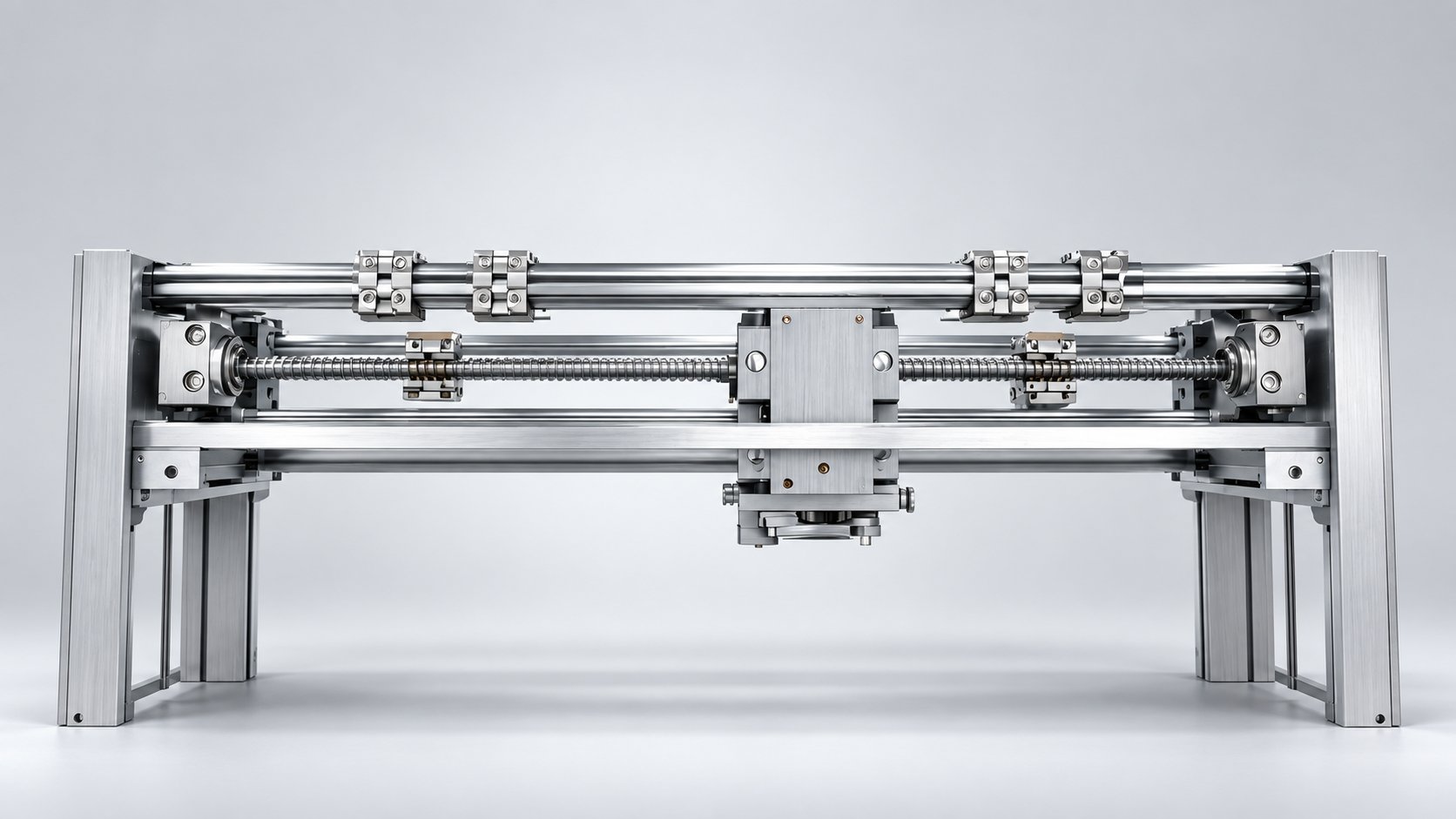
Ball screw whip is the bowing and vibration of a rotating screw between its supports as speed rises. This guide explains the physics, why unsupported length and end fixing decide the critical speed, and how engineers can specify supports and speed limits to avoid it.
A long, slender ball screw that runs smoothly at low speed can start to bow and shake as rpm climbs. Engineers often describe the symptom as a wobble or a whirling motion that grows with speed, then settles or disappears when the screw slows down. That behaviour is ball screw whip, and it is one of the most common reasons a positioning axis cannot reach the speed its motor and drive were sized for.
What this article covers
What ball screw whip actually is
A ball screw is a rotating shaft. Even a ground, straight screw has a small amount of natural bow, and it is supported only at its ends (and sometimes at an intermediate point). When the screw turns, any residual bow creates a centrifugal effect: the middle of the screw wants to swing outward. At low speed the restoring stiffness of the screw dominates and nothing visible happens. As speed increases, the centrifugal force grows with the square of rotational speed, while the screw's ability to resist bending stays roughly constant.
At a certain speed the two balance, and the screw becomes dynamically unstable. The middle of the screw orbits around the axis of rotation instead of staying on it. That orbiting motion is whip. It is not the same as backlash, lost motion, or a bearing fault, although on a real machine the vibration it creates can be mistaken for those problems.
The speed at which this instability begins is the critical speed of the screw assembly. It is a property of the whole rotating system, not just the screw: the screw's diameter and length, how its ends are held, and whether there is any intermediate support all feed into it. Running below the critical speed keeps the screw stable; running at or above it lets whip develop.
Why unsupported length dominates the problem
Of all the factors that affect critical speed, the unsupported length of the screw is the most powerful. The relationship is not linear. A screw's resistance to bending falls very steeply as the free span between supports increases, while the mass that must be controlled grows. The practical consequence is that a modest increase in unsupported length produces a large drop in the speed at which whip begins.
This is why whip is rarely a problem on short axes and almost always a consideration on long ones. A screw that is generously sized in diameter for the load it carries can still whip if the span between its supports is long, because diameter helps stiffness but length hurts it far more.
Two related effects make long screws worse:
- Sag under their own weight. A long horizontal screw bows downward between supports even when stationary. That initial bow gives the centrifugal force something to amplify once rotation starts.
- Lower natural frequency. A longer span has a lower bending natural frequency, so the screw reaches its unstable region at lower rotational speed.
In practice, the unsupported length is set by the machine layout: the stroke the axis must cover plus the bearing and nut envelope. Reducing it usually means changing the mechanical design, not the control parameters. That is why whip is best addressed at the specification stage.
How end fixing changes the critical speed
The way the screw ends are held changes how much of the screw can move. A rigidly fixed end resists both rotation and bending, so it behaves like a stiffer support. A simply supported end (for example a bearing that carries radial load but allows the screw to pivot slightly) provides less restraint. The same screw, same span, same diameter will have a higher critical speed when its ends are more rigidly fixed.
This is one of the reasons end-bearing selection is not only about axial load capacity. The bearing arrangement and housing stiffness determine how effectively the screw is held, and therefore how much of the theoretical stiffness is actually available at speed.
| End support condition | Effect on bending restraint | Practical implication |
|---|---|---|
| Both ends rigidly fixed | Highest restraint | Highest critical speed for a given span and diameter |
| One end fixed, one end supported | Moderate restraint | Common compromise between stiffness and thermal growth allowance |
| Both ends simply supported | Lowest restraint | Lowest critical speed; whip appears earlier |
The right choice depends on the application. A machine that must hold tight positioning accuracy over a long stroke may need rigidly fixed ends and a preloaded bearing set, while an axis with significant thermal expansion may need one end free to move axially. Both decisions interact with critical speed and should be evaluated together.
Practical ways to reduce or avoid whip
There is no single fix. In most machines, engineers combine several of the following measures.
Reduce the unsupported length
The most effective change is to shorten the free span. Options include adding an intermediate support, moving the bearing positions closer together, or rethinking the axis layout so the screw does not have to span the full travel unsupported. Any of these raises the critical speed substantially because of the strong length dependence.
Increase screw diameter
A larger diameter raises stiffness and therefore raises critical speed. The trade-off is higher inertia, which increases the torque needed to accelerate the screw and can affect motor sizing. Diameter is a useful lever when the span cannot be shortened, but it should be evaluated against the drive's acceleration capability.
Use a stiffer end-fixing arrangement
Upgrading from simply supported to rigidly fixed ends, or improving housing and bearing stiffness, raises the critical speed without changing the screw itself. This is often the cheapest change if the machine design still allows it.
Add an intermediate support or follower
For very long screws, an intermediate support or a travelling steady can break the span into shorter sections. Each section has its own higher critical speed. The design must account for how the support moves with the nut and how it is guided, so this is a mechanical design decision rather than a retrofit.
Limit operating speed
If the mechanical layout cannot be changed, the remaining option is to keep the axis below its critical speed. This is a control-level decision: the commanded rapid and positioning speeds must stay within the stable range, with margin for the fact that the critical speed depends on the actual end fixing and mounting stiffness.
Consider a different transmission for very long strokes
Where the required speed and stroke together make whip unavoidable, a rack and pinion or belt-driven axis may be more suitable. This is a system-level choice, but it is worth raising early rather than discovering the limit after the machine is built.
How to diagnose whip on a running machine
Whip has a recognisable signature. It is worth confirming before changing hardware.
- Speed dependence. Vibration grows as speed increases and reduces when speed drops. If the vibration is present at all speeds, look elsewhere first.
- Position dependence. The worst vibration often occurs when the nut is near mid-span, where the unsupported length is greatest.
- Direction. Whip produces a whirling motion, so vibration may appear in both radial directions rather than one.
- Audible and visible symptoms. A low-frequency rumble or a visible bow in the screw during a rapid move supports the diagnosis.
These signs distinguish whip from backlash, a damaged bearing, or a loose coupling, but they are not proof. A measurement of vibration versus speed, combined with the machine's actual support configuration, is the reliable way to confirm it.
What to confirm with your supplier
Critical speed depends on the specific assembly, so the number that matters is the one calculated for your screw diameter, your unsupported length, and your end-fixing arrangement. When specifying, it helps to provide:
- The maximum travel and the intended unsupported span between supports
- The end-fixing arrangement at each end, including bearing type and housing stiffness assumptions
- The maximum operating speed the axis must reach, and how often
- Whether an intermediate support is possible in the machine layout
- The required positioning accuracy and the load the screw must move
With those inputs, the supplier can calculate the critical speed for the actual configuration and recommend a diameter, end fixing, and speed limit that keep the axis stable. Treat any general figure as a starting point only; the correct value is configuration-specific.
FAQ
Is ball screw whip the same as critical speed?
Whip is the physical behaviour you see; critical speed is the speed at which that behaviour begins for a given screw assembly. They describe the same phenomenon from two angles.
Does a larger diameter always solve whip?
Larger diameter raises critical speed, but it also raises inertia and the torque needed to accelerate the screw. It helps, but it is not always the best or most economical fix compared with shortening the unsupported span.
Can whip be fixed by tuning the drive?
Control tuning can reduce the speed at which the axis operates and can damp some vibration, but it cannot change the screw's mechanical stability limit. If the required speed is above the critical speed, the mechanical arrangement has to change.
Why does the vibration get worse near mid-stroke?
At mid-stroke the nut is farthest from the supports, so the unsupported length is at its maximum and the screw is at its least stable. That is where whip is most likely to appear first.
The bottom line
Ball screw whip is a stability limit set mainly by unsupported length and end fixing. It is predictable, and it is best handled during specification rather than after the machine is running. Shorten the free span where possible, use the stiffest end fixing the application allows, size the diameter against the drive's acceleration capability, and confirm the critical speed for the actual configuration with your supplier before committing to a maximum operating speed.