
A decision guide for specifying bearing rails: integrated SBR round-shaft units, HGR profile guideways with carriages, and bare shaft with LM ball bushings, compared on load, precision and mounting conditions.
Linear Motion Selection
Bearing rails are sold in three practical configurations: a round shaft already mounted in an aluminum support with a bearing block, a profiled guideway matched to a carriage, and a bare shaft that runs in a separate ball bushing. The differences in how they carry load, how they are mounted, and how precisely they locate a moving member decide which one belongs in your machine.
- The three systems and what each one includes
- Load direction and capacity as the first filter
- Precision and mounting tolerance conditions
- Mounting interface, travel length and service
- Specifying your requirement and what to confirm
What "bearing rails" means in practice
When a buyer searches for bearing rails, the requirement behind the term is usually a linear axis that carries a load and guides it along a straight path. The bearing is either built into the rail assembly or supplied as a separate bushing that runs on a shaft. Each arrangement changes what the machine builder has to design around: the number of mounting holes, the height of the rail, the load the block or carriage can take, and the accuracy that can be held over the length of travel.
Dongfeng Bearing lists three families that cover most of these requirements. The sections below treat them as alternatives to be tested against your application rather than as a catalogue to browse by size alone.
System 1: integrated round-shaft units (SBR)
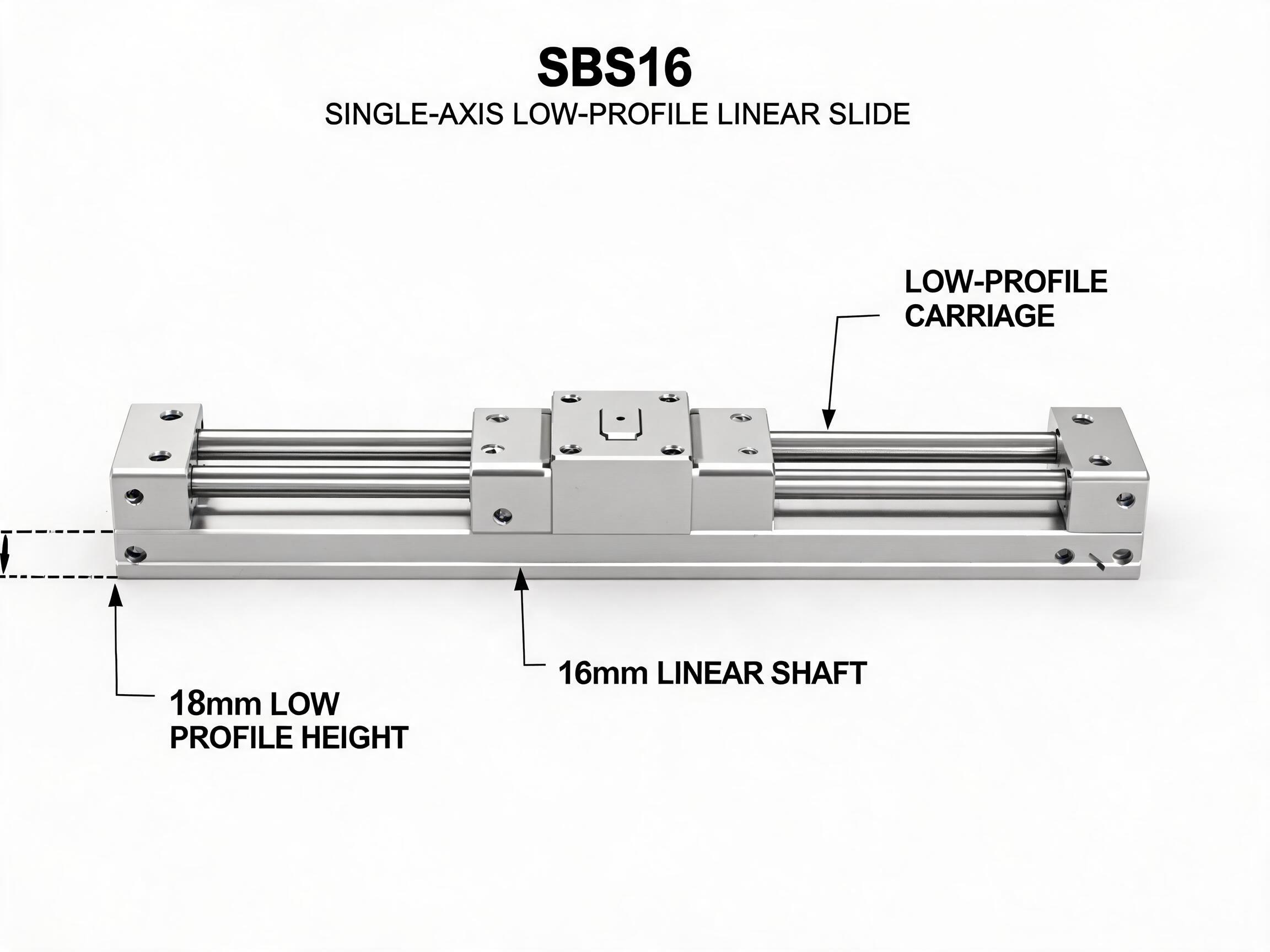
An SBR unit is a complete package: a hardened round shaft fixed into an aluminum support rail, with a bearing block that slides along it. The support rail carries the mounting holes for the machine frame, and the block bolts to the moving part.
In the SBR16 integrated linear guide rail unit with bearing block, the shaft is 16 mm in diameter and made of GCr15 bearing steel, hardened to HRC 58-62. The bearing block uses a double-row bearing arrangement and is rated for 7.8 kN dynamic load and 12.0 kN static load. Mounting holes are spaced every 50 mm along the standard 2000 mm length, with 4x M5 bolts holding the block. Custom lengths up to 4000 mm are available, and the SBR series covers 12, 16, 20, 25 and 30 mm shaft sizes.
For heavier carriage loads, the SBR20 heavy-duty linear motion guide unit with dual bearing blocks uses a 20 mm shaft. Each block is rated 11.2 kN dynamic and 17.5 kN static; running two blocks on one axis gives a listed 22.4 kN dynamic capacity for that axis. Standard length for this unit is 3000 mm.
The decision case for SBR is straightforward: when you want shaft, support and bearing block as one part number, the shaft is supported continuously along its whole length rather than only at the ends, and the mounting surface is the extruded aluminum support that already contains the hole pattern. You avoid designing a separate shaft-end support and a separate block housing.
System 2: profile guideway rails with carriages (HGR)
A profile guideway is a hardened rail with a ground raceway profile, matched to a carriage that fits onto that profile. The rail is mounted flat on a machined surface and the carriage carries the moving load. Load is shared across four rows of balls in the carriage, and the carriage surrounds the rail rather than sitting on top of a round shaft.
Dongfeng Bearing's HGR series heavy-duty linear guideway rail uses a four-row ball circuit and is offered in sizes 15, 20, 25, 30, 35 and 45. The H series is supplied in ground (P5) precision. The HGR20 size is listed at 16.7 kN dynamic and 26.7 kN static, and rails can be supplied up to 4000 mm. Matching carriage part numbers and their individual load ratings should be confirmed on the carriage datasheet, because the capacity of the axis is the combined result of rail and carriage selection.
The decision case for HGR is when precision location and stiffness matter more than the simplicity of a supported round shaft. A ground profile rail held to P5 grade gives the machine builder a datum to work from. The trade-off is installation: the mounting surface must be flat and aligned to the same standard you expect the carriage to hold, and the rail and carriage must be specified together.
System 3: bare shaft with ball bushings (LM)
An LM ball bushing is a separate bearing that slides over a plain shaft. The shaft is supported by the machine frame at its ends or at intermediate points you design, and the bushing housing is part of the moving assembly. This is the most flexible arrangement because the shaft and the housing are independent, but it also puts more design work on the machine builder.
The LM series linear ball bearing bush covers shafts from 6 mm to 60 mm and is offered in closed UU and open OP types. The open type allows the shaft to be supported along its length where a continuous support is used. The LM16UU example is listed at 980 N dynamic load.
The LM16UU figure is useful for scale: it is a single bushing on a 16 mm shaft, while the SBR16 block on the same 16 mm shaft diameter is rated at 7.8 kN dynamic. The SBR figure reflects a supported rail and a double-row block, so the two numbers answer different questions. If your load is above the bushing rating, the bushing is not undersized by accident; it is being used outside its role. Choose the arrangement that matches the load path you actually have.
The decision case for LM is when you need a custom shaft layout, want a housing you design yourself, or need a bushing that can be replaced without replacing the shaft. Where a shaft cannot be supported continuously, the shaft deflection and the resulting alignment have to be checked by you, not assumed from a catalogue.
Comparing the three families
| Condition | SBR integrated unit | HGR profile guideway | LM shaft and bushing |
|---|---|---|---|
| What is supplied as one item | Shaft, aluminum support rail and bearing block | Rail and carriage specified as a pair | Shaft and bushing supplied separately |
| Load path | Block on top of a continuously supported round shaft | Carriage wrapping a profiled rail on four ball rows | Bushing around a shaft; shaft support designed by builder |
| Listed capacity example | SBR16: 7.8 kN dynamic, 12.0 kN static per block | HGR20: 16.7 kN dynamic, 26.7 kN static | LM16UU: 980 N dynamic |
| Precision basis | Supported shaft; check straightness and height with the datasheet | Ground H (P5) precision | Dependent on the shaft and housing you provide |
| Mounting work | Bolt support rail to frame; holes every 50 mm on SBR16 | Machined flat, aligned rail mounting surface | Shaft supports and housing both designed by builder |
| Typical reason to choose it | Simplest complete axis with a supported shaft | Precision and stiffness with a defined datum | Custom layout and replaceable bushing |
Any figure not listed in the table for your candidate size should be taken from the datasheet for that exact part number. Do not carry a rating from one size or one block count across to another.
Using load direction to make the first cut
Start with the direction of the load relative to the rail. A bearing block or carriage has a rated capacity for a given load direction; where the load pulls up, sideways or at an angle, the effective rating can differ from the headline number, and the datasheet or supplier should be asked which direction the figure applies to.
Where the load is primarily downward and the shaft can be supported along its length, an SBR unit is the simpler path because the support rail does that job. Where the load has to be carried in more than one direction or the carriage must resist tilting moments, the four-row ball circuit of a profile guideway carriage is the arrangement to examine. Where the moving load is modest and the housing geometry is yours to define, an LM bushing with a shaft you support yourself may be the fit.
Two blocks on one SBR axis are a documented way to raise axis capacity: the SBR20 dual-block unit lists 22.4 kN dynamic per axis against 11.2 kN dynamic per single block. Whether that configuration suits your machine also depends on the distance between the blocks, which you choose, and on the moment the carriage has to resist.
Precision and mounting tolerance conditions
Precision claims belong to the parts that carry them. The HGR H-series rail is listed as ground (P5) precision, which is a property of the finished rail. The SBR unit's accuracy depends on the supported shaft in its aluminum rail and should be read from the SBR datasheet for your size and length. An LM bushing's running accuracy depends on the shaft you mount and the housing you machine.
Mounting tolerance is the other half of the decision. A profile guideway needs a flat, aligned mounting surface or the carriage will not run as the rail was ground. An SBR support rail needs a flat frame surface along its hole pattern. An LM arrangement needs shaft supports at the spacing you define, and the shaft must be straight and parallel to the intended travel. If you cannot machine or align a flat surface to the standard the chosen part expects, a supported round shaft is the more forgiving of the two rail-based options to install.
Travel length, joints and service
Length is a real selection condition, not a footnote. The SBR16 unit is 2000 mm standard with custom lengths to 4000 mm; the SBR20 unit is 3000 mm standard; HGR rails are supplied up to 4000 mm. Where a longer travel is needed, the joint detail between rail sections has to be agreed with the supplier, because the carriage crosses each joint and the joint is part of the running surface.
Service access differs too. An SBR bearing block can be unbolted from the moving part; a profile carriage is usually retained on the rail by its end seals and must not be slid off the rail end without the supplier's handling instruction. An LM bushing can be replaced on the shaft if the housing is designed for it. These differences matter for machines that will be maintained in the field.
How to state your requirement
A useful enquiry fixes the conditions and leaves the alternatives visible. State the load and its direction, the travel length, the mounting surface you can provide, and the accuracy you need the moving member to hold. Then name the family you are leaning toward and ask for the datasheet figures for that size.
A hypothetical example shows the shape of the request: an axis carrying a load downward over 1.5 m of travel, mounted on an existing flat frame, needing a simple bolt-on assembly. Stating it that way points to an SBR unit, and the buyer then confirms the shaft size against the block rating for the load direction. If the same axis had a tilting moment and a stricter locating requirement, the same enquiry would lead to a profile guideway and carriage pair, and the buyer would confirm carriage ratings and mounting-surface tolerance with the supplier.
For any figure that decides the build, ask Dongfeng Bearing for the datasheet for the exact size, block count and length you intend to order. The catalogue ratings above apply to the listed part numbers and sizes; they are not interchangeable between them.
Key takeaways
- SBR gives you a supported round shaft, mounting rail and bearing block in one part number; SBR16 is 7.8 kN dynamic, SBR20 with dual blocks is 22.4 kN dynamic per axis.
- HGR is a ground (P5) profile guideway; HGR20 is listed at 16.7 kN dynamic, and the carriage must be specified as a pair.
- LM bushings suit custom shaft layouts; LM16UU is listed at 980 N dynamic on a 16 mm shaft.
- Load direction and mounting-surface tolerance decide more than the headline load number.
- Length limits and rail joints must be agreed with the supplier before ordering long travel.