
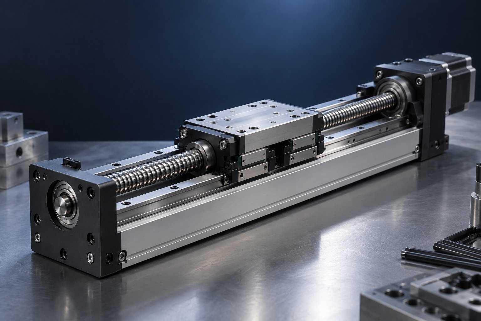
A mismatch between the guideway, drive screw, and bearings will show up as vibration, poor repeatability, or short life. This guide explains which decisions bind together, the trade-offs that matter, and the axis parameters you need to prepare before requesting component recommendations.
Building a linear actuator means committing to three components at once: the guideway that carries the load, the screw that drives it, and the bearings and support blocks that hold everything in alignment. Change one and the other two have to be re-checked. This guide explains the couplings between those decisions, the mismatch errors that appear on the bench, and the parameters to prepare before you request component recommendations.
Key takeaways
- Screw lead sets the speed–precision trade-off; resolution and repeatability are different specifications.
- Guideway type and preload determine load capacity and rigidity, not just mounting convenience.
- Bearing and support choice affects alignment, and alignment errors shorten life faster than load does.
- Mismatches usually show up as vibration, poor repeatability, or noise at certain speeds.
- Prepare an axis parameter list — stroke, load, speed, duty, environment — before asking for recommendations.
Why the three decisions are coupled
A linear actuator is a system, not a bill of materials. The screw decides how fast the carriage can move and how finely it can be positioned. The rail decides how much load that carriage can carry without deflecting. The bearings and support units decide whether the screw and rail stay parallel enough for the carriage to travel freely. If any one is specified in isolation, the other two will absorb the error — usually as heat, noise, or shortened life.
Guideway: load capacity and rigidity come first
The guideway sets the structural ceiling of the axis. Profile rail guides with recirculating balls or rollers are the common choice for machine axes because they can carry load in several directions at once, including moment loads. The main selection questions are:
- Load direction: is the load mainly downward, or are there side and moment loads from an offset tool or payload?
- Rigidity: cutting, pressing and pick-and-place applications need different stiffness. Preload raises rigidity but also raises friction and running temperature.
- Travel and support spacing: long unsupported spans deflect under their own weight, so block spacing and rail mounting must be part of the calculation.
Linear guideways and linear bearings are specified as a matched pair by size, preload class and accuracy grade. Moving up one preload class can noticeably change drag torque, which the drive screw then has to overcome.
Drive screw: the speed–precision trade-off
The screw converts rotation into linear motion. Ball screws are common in actuators that need both reasonable speed and good positioning, because recirculating balls reduce friction compared with sliding screws. Two numbers matter most:
- Lead: distance travelled per revolution. A larger lead gives more speed per motor revolution but reduces the force available and the resolution per step.
- Diameter: a larger diameter carries more axial load and resists buckling and whip at higher speeds, but adds rotating inertia.
The practical trade-off is straightforward. High lead plus a low-resolution drive gives fast but coarse motion. Low lead plus the same drive gives fine positioning but limits throughput. Whichever way you go, the screw must be matched to the motor torque available at the required acceleration, not only at steady speed.
Ball screw support units matter as much as the screw itself. A fixed-end support handles axial load and thrust; a supported end keeps the screw aligned and reduces sag over long spans. Using a simple end support where a fixed support is required is a common cause of backlash and poor repeatability.
Bearings and supports: alignment and life
Bearings keep the moving elements separated and located. In a linear actuator, this covers the linear bearings in the carriage, the angular contact or thrust bearings inside the screw support, and the bearing seats in the housing. Three points decide whether the axis runs well:
- Parallelism: the screw axis and the rail must be parallel within the housing's tolerance. Misalignment forces the carriage to fight the screw, which shows up as vibration and uneven wear.
- Preload: preloaded bearings remove play and raise stiffness, which improves repeatability. Excess preload raises friction and temperature.
- Lubrication and sealing: contamination is a life-limiting factor in most industrial environments. Seals and the lubrication route need to be chosen for the actual duty, not left to default.
Bearing steel hardness in the 58–62 HRC range is a widely referenced band for rolling elements and raceways in linear motion components; if a supplier states a hardness figure, ask which part it applies to and how it was measured. Hardness alone does not describe life — load, lubrication, alignment and contamination all contribute.
Common mismatch mistakes
| Mistake | What it looks like on the bench | What to re-check |
|---|---|---|
| High-lead screw paired with a drive that cannot resolve small steps | Fast moves, but positioning is inconsistent; fine adjustment is impossible | Lead, drive resolution, and the required positioning tolerance |
| Rail and screw specified independently, then assembled | Carriage binds at one end of travel; current rises with position | Parallelism of screw and rail, and mounting surface flatness |
| Standard end support used where a fixed support is needed | Backlash, poor repeatability, screw moves axially under load | Support type, axial load direction, and preload method |
| Preload selected for stiffness without checking friction | High running temperature, motor overload, short lubrication interval | Drag torque, duty cycle, and lubrication plan |
| Rail size chosen from catalogue load rating only | Deflection or vibration under real moment loads | Load direction, moment load, block spacing, and rigidity requirement |
Build-order checklist
Work through the axis in this order. Each step constrains the next, and going back is cheaper than rebuilding.
- Define the motion requirement: stroke, maximum speed, acceleration, positioning tolerance and repeatability target.
- Define the load: mass, centre of gravity, moment loads, and whether loads are static, dynamic or shock.
- Select the guideway type, size, preload and accuracy grade to meet load and rigidity.
- Select the screw lead and diameter to meet speed, force and resolution, then choose the support arrangement.
- Select bearings, preload and sealing to match the environment and duty cycle.
- Check alignment and mounting tolerances for the complete assembly, including the base structure.
- Confirm lubrication, protection and maintenance access before finalising the design.
A useful cross-check: calculate the force required to accelerate the load and compare it with the force the selected screw can deliver at the chosen lead. If the margin is thin, the axis will be sensitive to friction from preload and sealing.
What to prepare before requesting component recommendations
Suppliers can only recommend the right combination when the axis parameters are clear. Prepare the following for each axis:
- Motion profile: stroke, maximum speed, acceleration and deceleration, and duty cycle.
- Load data: moving mass, payload, centre of gravity offset, and direction of loads including moments.
- Accuracy: required positioning tolerance and repeatability, and whether these are at the carriage or at the tool.
- Drive: motor type and torque, coupling method, and whether the screw is driven directly or through a belt or gearbox.
- Environment: temperature range, dust, chips, coolant, washdown, and any cleanroom or vacuum requirement.
- Mounting: orientation (horizontal, vertical, inclined), available space, and the flatness and material of the mounting surface.
- Life and maintenance: expected hours or cycles, lubrication access, and whether the axis will be serviced in place.
With these inputs, a supplier can propose a guideway, screw and bearing set that works as a system rather than as three separate line items.
Supplier-side quality checks
When comparing components, ask what is actually verified and how. Useful questions include:
- Which dimensional and running tests are performed on the guideway, screw and support units before shipment?
- What hardness specification applies to the rolling elements and raceways, and at what point is it measured?
- Is preload set and checked per unit, or only declared as a class?
- What documentation accompanies a shipment, and what is the warranty period and its scope?
Xiamen Dongfeng Bearing has supplied linear guideways, linear bearings, ball screws, ball screw support units and linear slide modules since 2014. The company operates under ISO 9001:2015 and offers CE and SGS documentation, with a 24-month warranty and OEM/ODM custom engineering. Buyers should confirm that the specific certificate, hardness report or test record applies to the exact product and batch being purchased.
FAQ
What is a linear actuator used for?
Linear actuators convert rotary motion into controlled straight-line movement. They are used wherever a load must be positioned, pushed, lifted or carried along a fixed path — for example in automation cells, packaging equipment, test rigs, and machine tools. The guideway, screw and bearings are selected according to the load and motion profile of that specific task.
How do I choose a linear actuator for a machine axis?
Start with the motion requirement and load data, then size the guideway for load and rigidity, the screw for speed and resolution, and the bearings and supports for alignment and life. The three choices interact, so they should be confirmed together.
Does a higher screw lead always mean a faster actuator?
Lead increases travel per revolution, but the achievable speed also depends on motor speed, acceleration torque and the load. A high lead can reduce the available thrust and make fine positioning harder.
Why does my actuator vibrate at certain speeds?
Vibration often comes from screw critical speed or whip, misalignment between screw and rail, or a preload and lubrication condition that changes with temperature. It is worth checking alignment and support arrangement before changing components.
Matching the rail, screw and bearings at the specification stage is cheaper than correcting an axis that binds or loses repeatability after assembly. If you are building or specifying a linear motion axis, prepare the parameters listed above and request component recommendations based on the complete motion profile — not on a single part number.