
A specification guide for buyers and engineers on how a ball-screw driven linear axis is driven and how its position is reported. It explains the separation between limit switches for end-of-travel protection and encoders or position sensors for closed-loop positioning, and shows why the axis, the drive and the feedback device must be specified as one system.
Motion System Specification
A ball-screw driven linear axis is only as useful as the decisions made about how it is driven and how its position is reported. This article separates the two questions, explains what the choice of feedback follows, and gives a short checklist for matching the axis, the drive and the feedback device before an order is placed.
In this article
- Two questions buyers often merge
- How motor rotation becomes linear travel
- End-of-travel protection
- Closed-loop position reporting
- Choosing feedback from the positioning requirement
- Matching the motor interface on the axis
- Selection checklist
- FAQ
Two questions buyers often merge
When a specification leaves the drawing office, two different requirements are frequently written as one line: "the axis must move to position and stop." That sentence contains a drive decision and a feedback decision, and they are not the same decision.
The drive question is how electrical energy from a drive or controller is converted into controlled rotation, and then into linear travel along the screw. The feedback question is what the control system knows about where the carriage actually is. A motor can be perfectly sized for the load and still leave the control system blind to position if no position sensor is fitted. Conversely, a position sensor can report carriage location accurately while the ends of travel remain mechanically unprotected if no limit switch is installed.
Keeping these two questions apart is the first step toward a specification that can be built, wired and commissioned without a redesign in the middle.
How motor rotation becomes linear travel
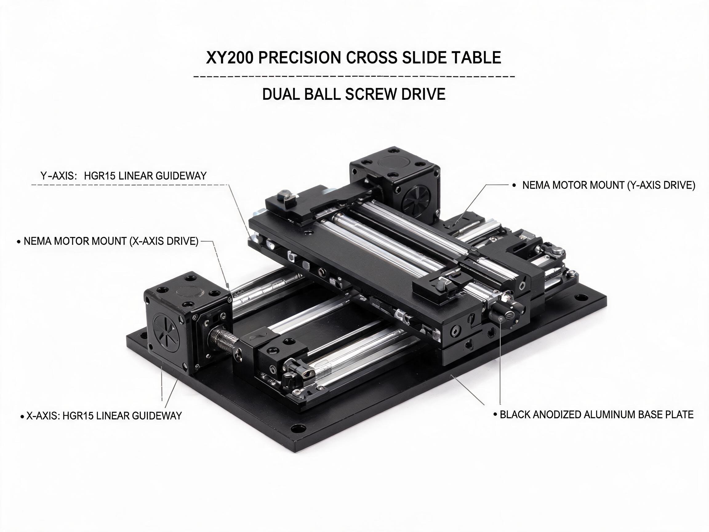
On a screw-driven axis, the motor rotates the screw, and the screw nut converts that rotation into linear motion of the carriage. The screw lead is the distance the nut travels for one full rotation of the screw. On the DFLinear XY200 Precision Cross Slide Table, each axis uses an SFU1605 ball screw with a 5 mm lead, so one screw revolution corresponds to 5 mm of travel. The screw is C7 grade with a lead accuracy of plus or minus 0.05 mm per 300 mm, and the table is specified for a positioning repeatability of plus or minus 0.01 mm per axis.
A useful engineering principle sits behind those numbers: resolution of commanded position is a property of the lead, the drive and the feedback combined, while repeatability is a property of the mechanical assembly. A finer lead produces smaller travel per revolution, but it also changes the torque and speed relationship the drive must satisfy. Neither effect can be judged from the lead alone.
Engineering principle: the screw lead converts motor rotation into linear travel. The drive, the screw and the feedback device together determine how precisely that travel can be commanded and confirmed.
The linear guide also matters for how faithfully the commanded position is reached. The XY200 pairs each screw with an HGR15 rail and an HGH15CA carriage, so the carriage is constrained along a defined axis rather than resting on a sliding surface. That constraint is what allows a repeatability figure to mean something in practice.
End-of-travel protection
Limit switches exist to protect the ends of travel. They are discrete devices: a switch is either actuated or it is not. When the carriage reaches the switch, the signal tells the drive or controller to stop or reverse before the nut runs into a hard stop. This is a safety and damage-prevention function, and it is separate from any question of where the carriage is in mid-stroke.
Two design points matter when limit switches are specified:
- They should be positioned so that the carriage triggers them before mechanical interference occurs, taking into account the overtravel the drive needs to decelerate.
- They belong to the axis as a protective layer, not as the primary position reference. Using a limit switch as a home or position sensor is a common specification error.
Engineering principle: limit switches protect the ends of travel. They do not, by themselves, support closed-loop positioning.
Closed-loop position reporting
Closed-loop positioning means the control system continuously compares commanded position with reported position and corrects the drive output accordingly. That loop needs a position sensor. An encoder mounted on the motor shaft reports motor rotation; from the lead, the controller can infer linear travel. A linear encoder or other position sensor mounted along the axis reports carriage position directly.
The two approaches answer different questions. Motor-mounted feedback tells the controller how the motor turned. Axis-mounted feedback tells the controller where the carriage is. Where backlash, screw wind-up or thermal growth between the motor and the carriage matters, the two readings can diverge, and the specification should say which one governs the acceptance criteria.
Engineering principle: an encoder or other position sensor is what supports closed-loop positioning. The choice between motor-mounted and axis-mounted feedback follows from what the positioning tolerance must account for.
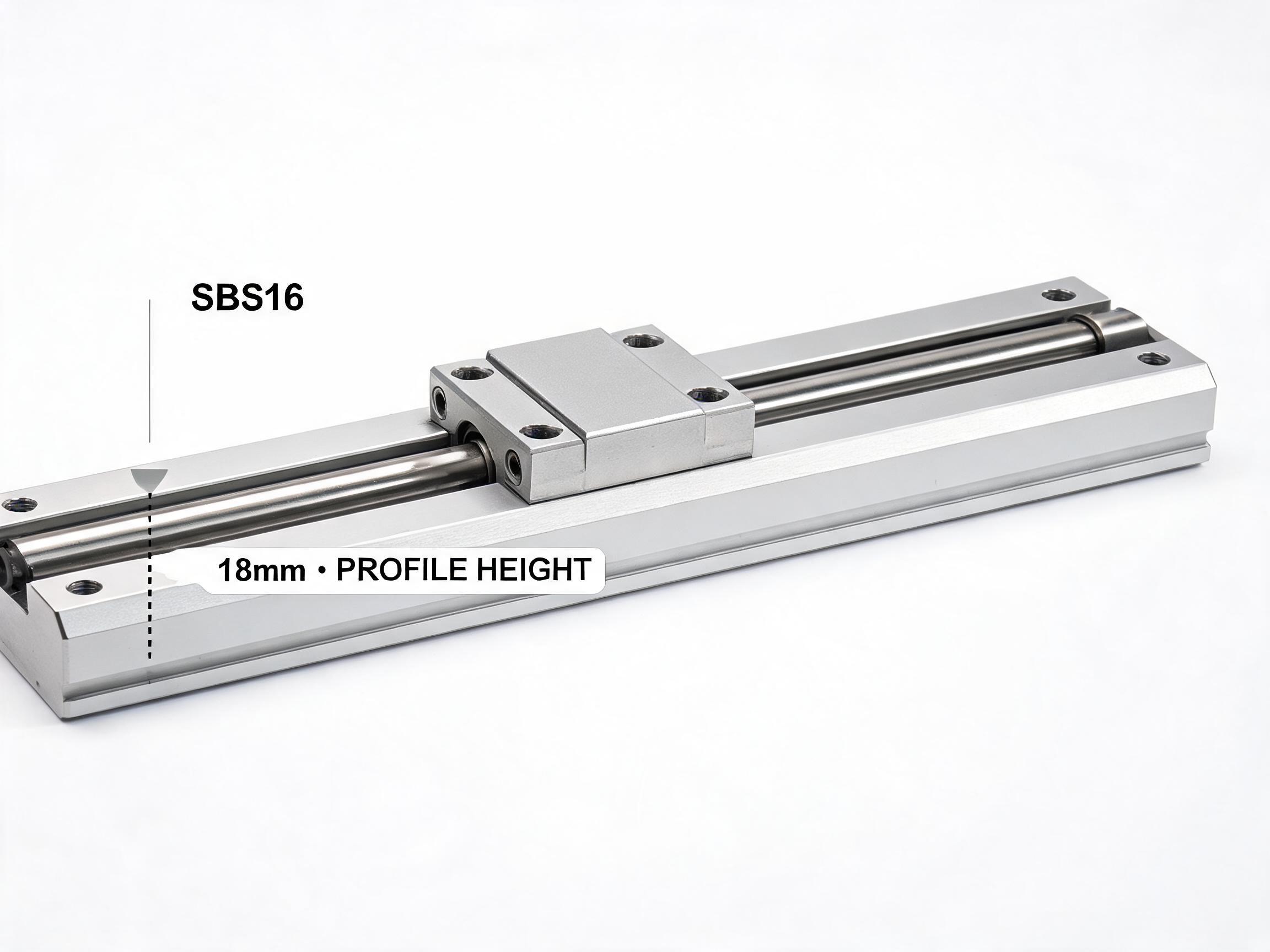
The DFLinear SBS16 Single-Axis Linear Motion Slide Unit is built on a 16 mm GCr15 chrome steel shaft, induction hardened to HRC 58 to 62, with a total system height of 18 mm. Its dynamic load rating is 5.2 kN and static load rating is 8.0 kN, with standard lengths from 150 to 500 mm and custom lengths up to 1000 mm. These figures describe the structural and load side of the axis; they do not by themselves determine the feedback architecture, which is a separate specification decision made alongside the drive.
Choosing feedback from the positioning requirement
A frequent mistake is to choose a feedback device first and then back-fill the axis specification around it. The more reliable sequence runs the other way. Start with the positioning tolerance the process requires, the duty cycle the axis will see, and the consequence of a positioning error. Then select the feedback class that can support those requirements, and confirm the axis and drive can carry that feedback device.
Engineering principle: feedback choice follows the required positioning tolerance and duty, not the other way around.
Three requirement profiles illustrate how the decision changes:
| Requirement profile | Primary need | Feedback implication |
|---|---|---|
| Move between two fixed stops, no intermediate positions | Prevent overrun at each end | Limit switches at both ends; position sensing may not be required for the motion itself |
| Repeated moves to defined intermediate positions | Confirm arrival and control the loop | Position sensor supporting closed-loop control, plus end-of-travel switches for protection |
| Position reporting that must reflect carriage location rather than motor rotation | Account for the transmission between motor and carriage | Axis-mounted position feedback, with the drive configured to use it |
These profiles are illustrative categories, not product specifications. The point is that the same axis hardware can be specified with different feedback arrangements depending on what the process actually needs to know.
Matching the motor interface on the axis
The axis, the drive and the feedback device must be specified as one system. A common source of commissioning delay is a motor that physically fits the load but cannot be mounted to the axis, or a drive that cannot accept the feedback signal the axis carries.
Engineering principle: the axis, the drive and the feedback device must be specified as one system.
The DFLinear XY200 illustrates the kind of interface detail that belongs in this check. It provides a NEMA 17 motor flange interface with an independent motor mount per axis. The independent mount per axis matters on a cross slide table because each axis can be set up and adjusted separately, rather than forcing a shared mounting geometry. A NEMA 17 interface also constrains the motor frame size the buyer can fit, so the motor and the mounting interface should be confirmed against each other before the drive is ordered.
Beyond the flange, the items worth confirming are the coupling between motor shaft and screw, the mounting arrangement for any feedback device, and whether the drive can be wired to accept both the position sensor and the end-of-travel switches.
Selection checklist
Work through these items in order. Each one depends on the answer to the one before it.
- State the positioning tolerance the process requires, and whether it applies to repeatability, to absolute position, or to both.
- State the duty cycle and the expected number of moves, so the drive and feedback class can be matched to it.
- Decide whether the motion needs only end-of-travel protection or closed-loop position reporting as well.
- If closed loop is required, decide whether motor-mounted or axis-mounted position feedback governs the acceptance criteria.
- Confirm the motor frame size against the axis mounting interface. On the XY200, that interface is NEMA 17 with an independent motor mount per axis.
- Confirm the drive can accept the selected feedback signal and the end-of-travel switch inputs.
- Check that the mechanical assembly can carry the feedback device without interfering with travel over the full stroke.
- Record which party is responsible for the loop tuning and the position verification, and against which reference.
For cross slide and single-axis configurations, the product pages for the XY200 Precision Cross Slide Table and the SBS16 Single-Axis Linear Motion Slide Unit list the mechanical specifications these decisions are built on.
FAQ
What is linear actuator feedback?
Linear actuator feedback is the signal a control system receives about the actuator's position or motion state. It comes from end-of-travel limit switches for protection, from an encoder or other position sensor for closed-loop positioning, or from both. Which of these is required depends on whether the application only needs to stop at the ends of travel or also needs to know where the carriage is at intermediate positions.
What is a linear actuator motor?
In a screw-driven linear axis, the motor is the rotary drive that turns the screw. The screw nut converts that rotation into linear travel. The motor is one part of a system that also includes the drive, the feedback device and the mechanical axis; specifying the motor without the other three leaves the positioning behaviour undefined.
Can I use limit switches instead of an encoder?
Only if the application does not require closed-loop positioning. Limit switches protect the ends of travel but do not report intermediate carriage position. If the process requires repeated moves to defined positions, a position sensor is also needed, and the limit switches remain as a protective layer.
Does a NEMA 17 motor mount limit my drive choice?
The NEMA 17 flange constrains the motor frame size that fits the axis. The drive is a separate selection, but it must be able to accept the feedback signal and switch inputs used by the axis. Confirm both together rather than selecting the motor and drive independently.
What determines the repeatability of the axis?
Repeatability is a property of the mechanical assembly, including the screw, the guide and the carriage. The XY200 is specified for a positioning repeatability of plus or minus 0.01 mm per axis, and ships with a CMM orthogonality report and repeatability test data so the buyer has a record of the as-built condition. Commanded resolution is a separate matter that also involves the drive and feedback.
If you are specifying a cross slide table or a single-axis slide unit and need to confirm the mounting interface, the screw lead or the as-built test documentation, send the positioning requirement and the intended drive arrangement. The mechanical specifications and the test data that ship with each unit are the right starting point for that conversation.