
Linear rails, shaft guide units, and rolled ball screws all move a CNC router's axes — but they don't do the same job. This guide compares load direction, rigidity, cost, and mounting requirements so you can match the right motion hardware to your build.
A router build stalls for the same reason more often than any other: the motion hardware was chosen by price or by habit instead of by load direction and build volume. This guide compares linear rails, shaft guide units, and rolled ball screws on the points that actually change how a router cuts — so you can match each axis to the job it has to do.
Key takeaways
- Linear profile rails carry load in all directions and resist the moment loads a gantry creates; shaft guide units (round rails with linear bearings) are best kept to lighter, shorter axes.
- Rolled ball screws are the standard choice for router X, Y, and Z axes; ground screws hold tighter lead accuracy but usually are not needed for wood, plastic, and aluminum routing.
- Rail size, preload class, screw diameter, and lead must be matched to axis length and cutting force — not selected as a package deal.
- Mounting flatness and parallelism are not installation details; they decide whether any rail or screw reaches its rated life.
Start with the loads, not the catalog
Every CNC router axis has to handle four load types at once: the weight of the gantry or spindle, the cutting force pushing against the tool, the moment that force creates at the bearings, and vibration from the cutter. A gantry router cutting a 3/4-inch bit through hardwood pushes back hard and in changing directions. A small desktop machine cutting engraving passes generates almost none of that.
That difference is why "which rail is best" has no single answer. The right question is which guide type carries the loads your axis will actually see, at the stroke length you need, without deflecting more than your cut tolerance allows.
Linear profile rails: the default for loaded router axes
Profile rails use a carriage that wraps the rail on four sides through recirculating balls or rollers. Because the carriage contacts the rail in multiple directions, the assembly resists downward load, side load, and the tipping moment that occurs when the cutting force acts at a distance from the rail.
Where they fit
- Gantry (X) and cross (Y) axes on machines with a moving gantry or a heavy Z assembly, where moment loads are highest.
- Long travel axes where a single rail plus a wide carriage pair can replace two round rails and still hold stiffness.
- Machines cutting aluminum or dense composites, where any deflection shows up as chatter or a tapered edge.
What to specify
- Rail width — 15, 20, 25, and 30 mm are common steps. Wider rail and carriage generally mean higher load rating and stiffness, but also more mounting height to account for.
- Preload class — light preload removes play for positioning accuracy; heavier preload adds stiffness but raises drag and cost. Match it to whether the axis is cutting or only positioning.
- Accuracy grade — grade affects running parallelism and height tolerance between rails. If two rails share one gantry, the grade of the pair matters more than the grade of either rail alone.
- Mounting surface — profile rails must sit on a machined, flat surface. A rail bolted to an unmachined extrusion will follow the extrusion's twist.
Shaft guide units: capable, but on the right axis
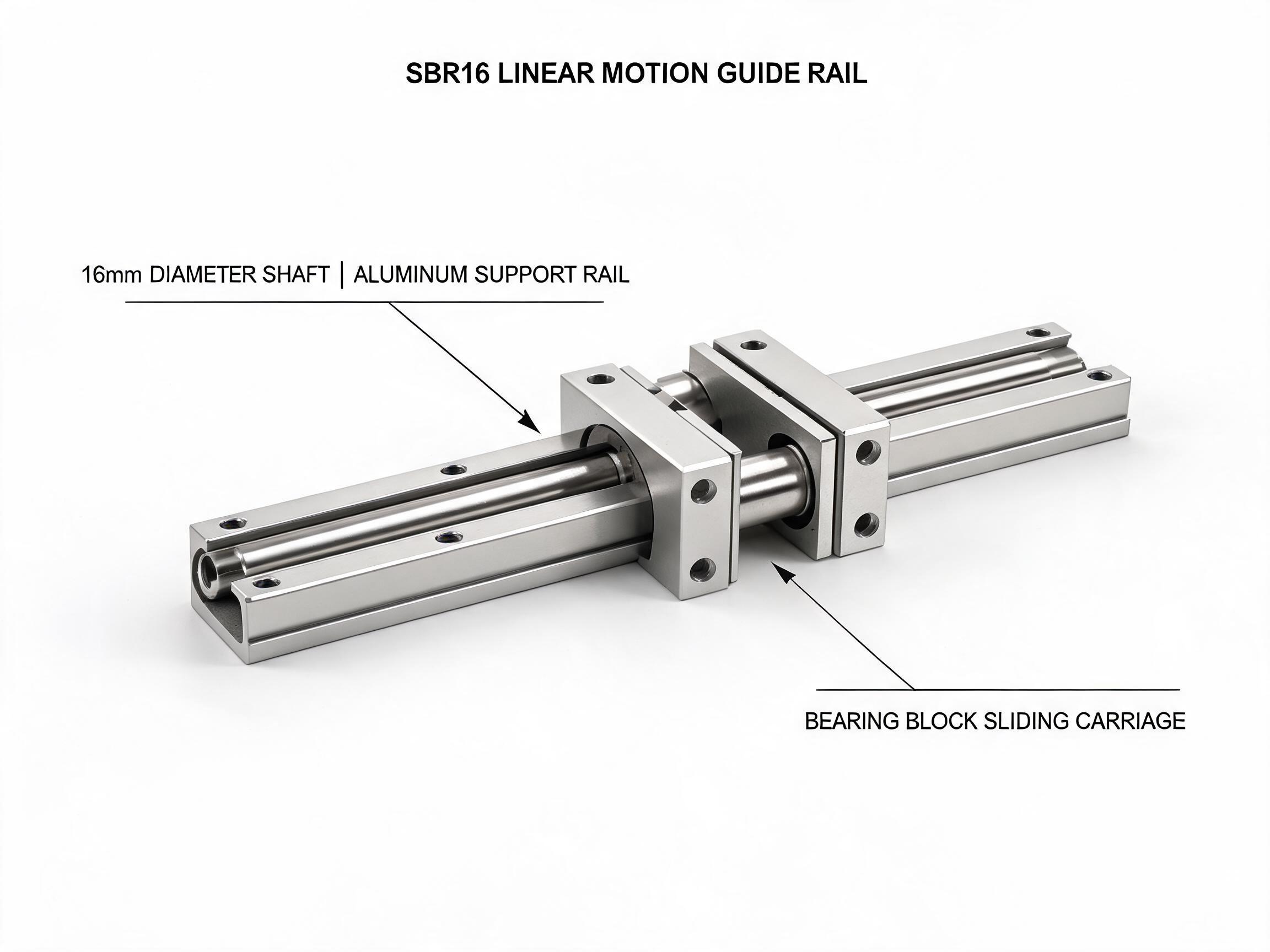
A shaft guide unit is a hardened round shaft paired with a linear bearing — either a plain bushing or a recirculating ball bushing. The round shaft can be supported along its length or left unsupported, and the bearing slides or rolls along it. A ready-assembled example is our SBR16 linear motion guide rail unit, which pairs a 16 mm GCr15 shaft hardened to HRC 58–62 with an aluminum support rail and bearing blocks — 7.8 kN dynamic load, usable up to 2,000 mm (4,000 mm custom).
The advantage is cost and simplicity: round shafts and bushings are widely available, easy to align in a simple frame, and forgiving on short strokes. The limitation is load direction. A standard round bearing carries load best in the direction it was designed for, and its resistance to moment load is lower than a profile rail of similar size. A long unsupported shaft also deflects under load, which changes the cut as the axis moves toward mid-stroke.
Where they fit
- Short Z or secondary axes where stroke is limited and the load is mostly axial.
- Light-duty or hobby-class machines cutting soft materials at modest depth.
- Applications where the frame already provides support along the shaft, reducing deflection.
If you are comparing a shaft guide unit against a profile rail for a loaded gantry axis: check the moment rating and the supported length first. A round rail that works on a 300 mm Z axis may deflect unacceptably on a 1,500 mm Y axis unless it is fully supported along its length.
Comparing the two guide types side by side
| Consideration | Linear profile rail | Shaft guide unit (round shaft + bearing) |
|---|---|---|
| Load directions carried | Down, side, and up; resists moment in all planes | Primarily one direction per bearing; lower moment capacity |
| Stiffness at long stroke | Holds stiffness along the full rail | Depends on shaft support; unsupported shafts deflect |
| Mounting demand | Requires flat, machined reference surface | Can be set in a simpler frame; alignment still matters |
| Typical cost position | Higher per axis | Lower per axis |
| Best-fit axis | Loaded gantry, cross, and long travel axes | Short or light axes; low-force machines |
Ratings and dimensions vary by series and manufacturer. Confirm the load and moment figures for the exact part number before committing to a design.
Ball screws: rolled versus ground
The ball screw converts motor rotation into linear motion. On a router, it sets the axis resolution and, together with the rail, the rigidity of the drive train. Two manufacturing routes dominate.
Rolled ball screws
A rolled ball screw is formed by rolling the thread form into the shaft rather than grinding it. The result is a screw with good surface finish and lead accuracy suitable for most routing work, at a lower cost than a ground screw. For wood, plastic, foam, and moderate aluminum cutting, a rolled ball screw is usually the practical choice for X, Y, and Z axes. For example, our SFU series rolled ball screw assembly is C7 grade (±0.05 mm per 300 mm) with a single-nut preload, available in lengths from 300 to 1,500 mm.
Ground ball screws
A ground screw is cut with an abrasive wheel to a tighter lead accuracy and is typically specified when the axis has to hold position very precisely over its length, or when the application demands low lead error. Ground screws cost more and are often longer-lead-time items. For the majority of router builds, the tighter accuracy is not the limiting factor — rail stiffness and frame rigidity usually are.
What to specify on a ball screw
- Diameter — a larger screw is stiffer and better resists buckling and whip on long axes.
- Lead — the distance traveled per revolution. A coarse lead gives fast rapid moves but lower force per motor torque; a fine lead gives more force but slower travel.
- Length and end machining — the screw must be supported by bearing blocks at the ends, and the end journals must match those blocks. Critically, a screw that is too long for its diameter will whip at speed.
- Preload and nut type — preload removes axial play; the nut flange must match the mounting pattern of the axis carriage.
Matching screw to rail and to axis length
The rail and the screw are not independent. They are both mounted to the same carriage and both see the same cutting force. The rule of thumb is to size the screw so it is not the weak link: if the rail is stiff but the screw whips at rapid speed, the machine will still chatter. On long axes, a larger-diameter screw with a coarser lead is often the better pairing; on short axes, a smaller screw with a fine lead can be appropriate.
Length matters twice. First, an unsupported or poorly supported screw can deflect and whip. Second, position accuracy over a long travel is harder to hold than over a short one, which is another reason to confirm the rated lead accuracy over the actual travel length rather than at a nominal figure.
Mounting and alignment decide the outcome
Two rails on one axis must be parallel to each other and flat to the mounting surface, within the tolerance the rail grade assumes. A ball screw must be parallel to the rails so the nut does not bind. These are not optional refinements — a system bolted to a warped weldment will wear prematurely no matter what grade was purchased.
- Machine or shim the mounting surface before installing profile rails.
- Check parallelism between rails and between screw and rails after tightening.
- Allow for thermal growth on long axes if the machine runs continuously.
- Verify running torque after assembly; a binding axis is an alignment problem, not a bearing problem.
FAQ
Can I use a shaft guide unit on a gantry axis?
It can work on short, lightly loaded gantries, especially if the shaft is supported along its length. On a long, loaded gantry cutting hard material, the lower moment capacity and shaft deflection usually make a profile rail the more reliable choice. Confirm the moment rating for the exact bearing and shaft support arrangement.
Do I need ground ball screws for wood routing?
Usually not. Rolled ball screws are the common choice for wood, plastic, and moderate aluminum work. Ground screws become relevant when the axis must hold very tight position over its travel or when the application specifies low lead error.
How do I choose the rail width?
Start from the load and moment the carriage must carry, then the available mounting height. A 15 mm rail may be adequate on a small Z axis, while a loaded gantry often calls for 20 or 25 mm and above. The rail width also affects carriage height, so it interacts with the rest of the axis design.
What is the most common specification mistake?
Selecting rail, screw, and bearing blocks as a matched kit without checking each against the axis length and cutting force. The second most common is installing profile rails on an unmachined surface. Both show up later as chatter, short bearing life, or inconsistent cut depth.