
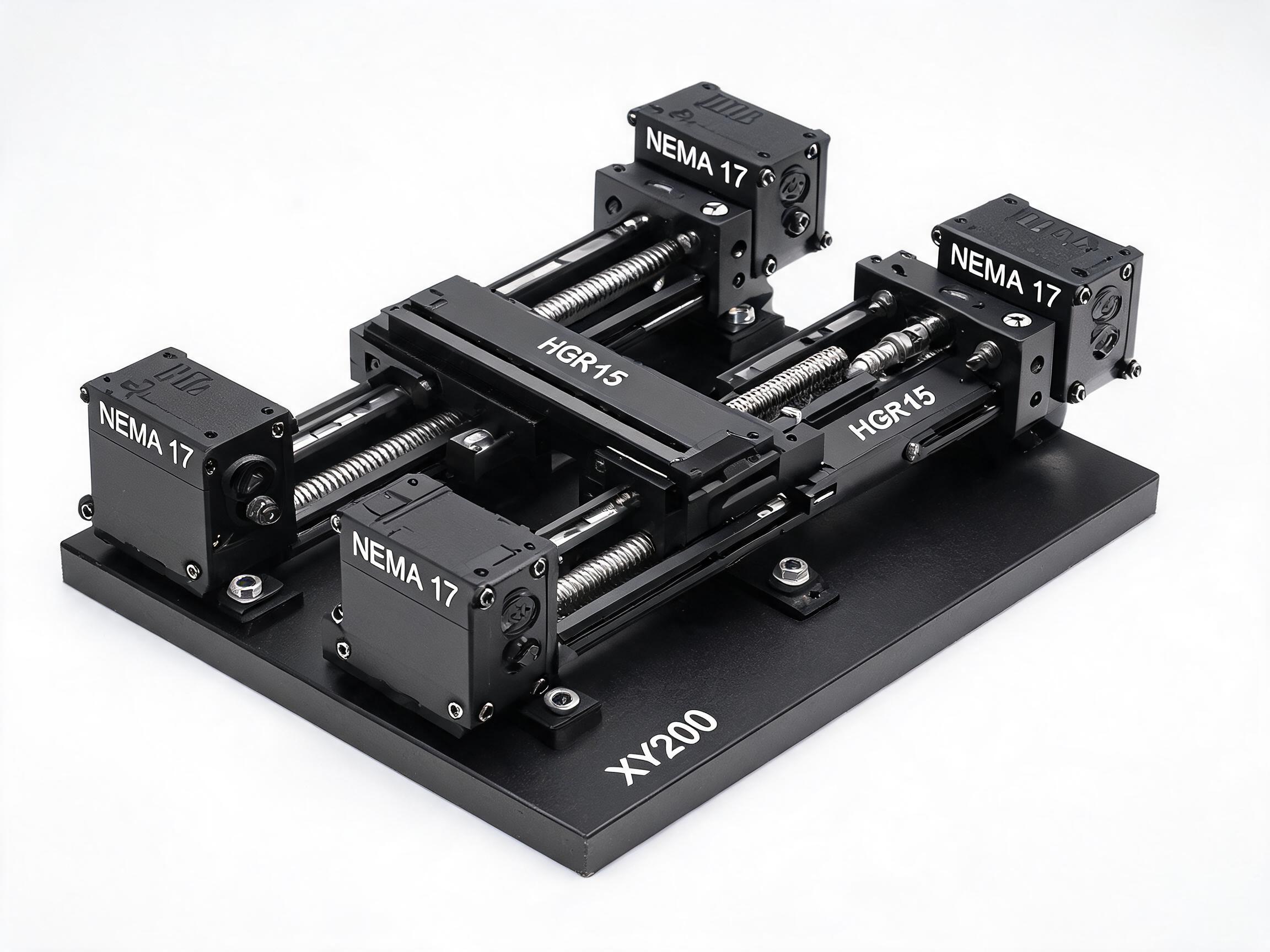
A practical commissioning sequence for engineers and buyers setting up a ball-screw driven motorized linear slide or XY cross slide table, covering the checks to complete before the first power-up and how to verify the as-delivered mechanical state against the supplier's inspection data.
A motorized linear slide does not run correctly because the carton arrived intact. It runs correctly because the mechanical state as delivered matches the inspection data shipped with the unit, and because the mounting interface absorbs load in a way that the rail and ball screw can tolerate. Most first-day problems on a commissioned axis trace back to steps that were skipped before power was applied, not to the drive electronics. This sequence applies to a ball-screw driven motorized linear slide or a cross slide table, and every check has a stated pass criterion.
Key takeaways
- Release the shipping clamps before any commanded motion.
- Verify as-delivered mechanical state against the supplier's report before connecting the motor.
- Confirm orthogonality, base flatness, rail parallelism, and ball screw lead against documented values.
- Record runout and backlash at hand rotation before the first power-up.
Pre-power-up checks in commissioning order
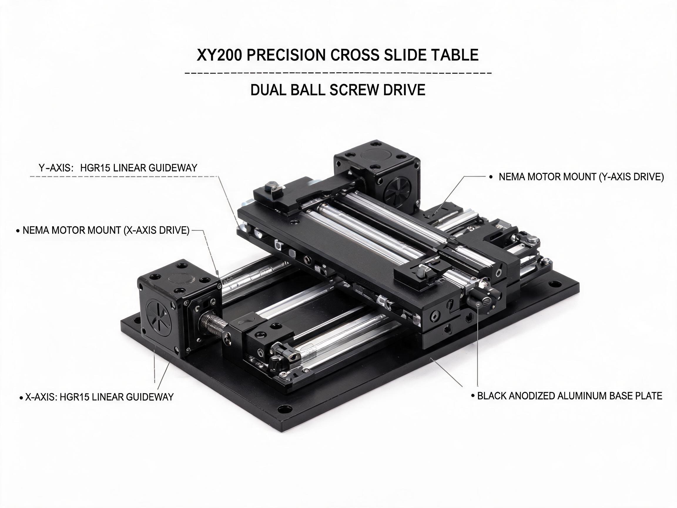
The following numbered sequence is written for a two-axis assembly such as the XY200 precision cross slide table with dual ball screw drive, where each axis carries an HGR15 rail with an HGH15CA carriage and an SFU1605 ball screw at C7 grade. The order matters: release clamps first, then inspect, then measure, then compare, and only then apply power.
-
Inspect the crate and retain the records. The unit ships in a foam-lined wooden crate with the axes retained in position, and it ships with a CMM orthogonality report and repeatability test data. Remove the top of the crate and confirm the report and data sheet are present and correspond to the serial number on the base plate. Do not discard the clamps or the report. Pass criterion: report and repeatability data present, serial number matching, no visible impact damage to the crate, base plate, rails, or ball screws.
-
Release the shipping clamps before any motion. Axes are locked with shipping clamps before dispatch and must be released before motion. Move the axis only by hand after the clamps are released; do not command motion from the controller until the clamp release is verified on both axes. Pass criterion: every clamp removed and stored, both axes move freely by hand at low force, and no clamp element remains in the travel path.
-
Confirm base plate flatness on the mounting surface. The base plate is 6061-T6 aluminium, black anodized, and ground to a flatness of 0.01 mm or better over 300 x 300 mm. Check the mounting surface with a straight edge and feeler gauge or a dial indicator on a surface plate if one is available, and inspect the machined face for dents or nicks introduced in transit. Pass criterion: no raised damage on the mounting face, and flatness consistent with the stated 0.01 mm or better over the 300 x 300 mm working area.
-
Check orthogonality against the CMM report. The two axes are arranged in an X plus Y cross configuration, and orthogonality is 90 degrees plus or minus 0.02 degrees as verified on a CMM. Before power-up, place a square or an indicator setup against the reference faces and compare the reading with the report value. Pass criterion: measured orthogonality within the reported 90 degrees plus or minus 0.02 degrees window, using the same reference features the supplier used.
-
Verify rail and carriage condition on each axis. Each axis uses an HGR15 rail with an HGH15CA carriage. Run the carriage over the full travel by hand and check for roughness, tight spots, or a change in drag at the end of travel. Inspect the rail for grit, chips, or a displaced wiper. For the carriage specification and flange geometry, refer to the HGH series flange type linear guideway carriage block page and confirm the carriage type matches the assembly you received. Pass criterion: smooth motion over the full travel with no binding and no change in feel that suggests contamination or rail misalignment.
-
Confirm ball screw lead and lead accuracy basis. Each axis uses an SFU1605 ball screw at C7 grade with 5 mm lead and lead accuracy of plus or minus 0.05 mm per 300 mm. Rotate the screw by hand and confirm that one full revolution of the screw produces 5 mm of carriage travel, measured against a reference or a dial indicator set up on the carriage. Pass criterion: measured travel per revolution consistent with the 5 mm lead, and any variation interpreted against the stated plus or minus 0.05 mm per 300 mm band rather than an unstated tighter value.
-
Measure hand-rotation backlash and free play. With the axis unpowered, hold the carriage and reverse the input by hand and observe lost motion. This establishes a baseline before a motor, coupling, or belt is attached. Pass criterion: repeatable lost motion, no intermittent catch, and a baseline recorded for later comparison once the motor is mounted.
-
Inspect the motor mount and flange interface. Each axis has an independent motor mount with a NEMA 17 motor flange interface. Confirm the mount is square to the screw axis and that the mount fasteners are tight and not bottomed. Confirm the interface matches the motor frame you plan to fit. Pass criterion: mount face square to the screw axis, fasteners torqued to the assembly specification, and flange pattern matching NEMA 17 without adapter shims that would introduce misalignment.
-
Record the as-delivered positioning baseline. Positioning repeatability is plus or minus 0.01 mm per axis, and dynamic load is 11.2 kN per axis. Before power-up, record the as-delivered condition of the axes, clamp state, and any measured values so that later readings can be compared against the supplier's repeatability test data. Pass criterion: a written baseline exists, is dated, and is traceable to the serial number and report.
-
Verify travel and overall envelope against the layout. At 200 mm travel, overall dimensions are 340 x 340 x 60 mm, and travel per axis is 200 mm with custom 100 to 500 mm available. Check that the mounting footprint, cable routing, and any enclosure or guarding in your machine clear the actual envelope. Pass criterion: the installed assembly fits the machine layout with travel, cable bend, and any guard clearance accounted for, using the ordered travel value rather than the 200 mm standard figure if a custom travel was supplied.
Comparing as-delivered state with supplier inspection data
The report and the hardware describe the same object. The purpose of the pre-power-up checks above is to confirm that the object in front of you still matches the object that was measured. Treat the CMM orthogonality report and repeatability test data as the supplier's record of that specific unit, and make each measurement on the hardware with the same reference features, the same measurement direction, and the same method the report states. When a reading falls outside the reported value, the first action is not to adjust the axis; it is to confirm the measurement method, because a different datum or a different probe position will produce a different number on a correctly built assembly.
The table below maps the check to the documented value so that the pass or fail decision is made against a stated figure rather than an expectation.
| Check | Documented value | How to verify before power-up |
|---|---|---|
| Base plate flatness | 0.01 mm or better over 300 x 300 mm | Straight edge and feeler gauge or dial indicator on the mounting face |
| Orthogonality | 90 degrees plus or minus 0.02 degrees | Square or indicator setup against reference faces, compared to the CMM report |
| Ball screw lead | 5 mm per revolution | Hand rotation measured against a carriage indicator |
| Lead accuracy | Plus or minus 0.05 mm per 300 mm | Compared against the stated band, not an assumed tighter value |
| Positioning repeatability | Plus or minus 0.01 mm per axis | Baseline recorded, to be compared after motor mounting |
| Dynamic load | 11.2 kN per axis | Checked against the applied load of the machine design, not measured on the bench |
| Rail and carriage | HGR15 rail with HGH15CA carriage | Visual and hand-travel inspection of each axis |
What to confirm on the mounting interface before power-up
Mechanical checks that pass on the bench can still fail once the axis is bolted into a machine. Three items decide most of the outcome.
- Mounting surface flatness. Bolting the 6061-T6 base plate onto a surface that is not flat will distort the plate and change the rail geometry. Confirm the machine mounting surface is at least as flat as the plate it carries.
- Fastener engagement. Using fasteners that are too long can bottom out in the base plate and lift the plate locally. Confirm thread engagement depth against the plate thickness at each mounting hole.
- Motor mount independence. Because each axis has an independent motor mount, the coupling between the motor and the ball screw must tolerate the small alignment difference between the two mounts. Confirm the coupling is fitted according to its own specification before energizing.
Only after these checks should power be applied. Apply the first motion at low command speed with the axis free of load, in a direction and distance you can observe, and be ready to stop the axis immediately. A first move that follows the command smoothly, without unusual noise or a jump, confirms that the mechanical state and the commanded direction agree.
Common questions at commissioning
Can I power the axis with the shipping clamps still installed?
No. The axes are locked with shipping clamps before dispatch and must be released before motion. Commanding motion against a clamp loads the ball screw, the carriage, and the motor coupling in a way the assembly was not built to accept, and any resulting damage will make it impossible to compare the axis against the as-delivered repeatability data.
What if my measured orthogonality differs slightly from the CMM report?
First confirm the measurement method and reference faces match the report, because a different datum or probe direction can shift the apparent reading on a correctly built assembly. If the reading, taken the same way, sits outside the 90 degrees plus or minus 0.02 degrees window, do not adjust the axis yourself; raise it with the supplier with your measurement record and the serial number.
How do I set up a linear actuator direction and travel for the first move?
Set a short move, in a direction you can watch, at a low command speed, with the axis unloaded and the clamps released. Confirm the carriage moves in the direction and distance you commanded before running the full travel. This first move verifies the mechanical state rather than the drive tuning.
Do I need the report later, after the machine is running?
Yes. The CMM orthogonality report and repeatability test data for the unit are the reference for any later drift or maintenance question. Store them with the machine records and reference the serial number when you contact the supplier.
Can I order a travel other than 200 mm?
Travel per axis is 200 mm as standard, with custom 100 to 500 mm available. Confirm the ordered travel value before checking the envelope and the mounting layout, since a custom travel changes the overall installed dimensions.
Next step after the first power-up
Once the machine is running, the pre-power-up record becomes the maintenance baseline. Keep the as-delivered measurements, the serial number, and the supplier's CMM orthogonality report and repeatability test data together. When a later reading drifts, compare it against that baseline and the stated values rather than against a remembered number, then raise the difference with the supplier with the record attached.