
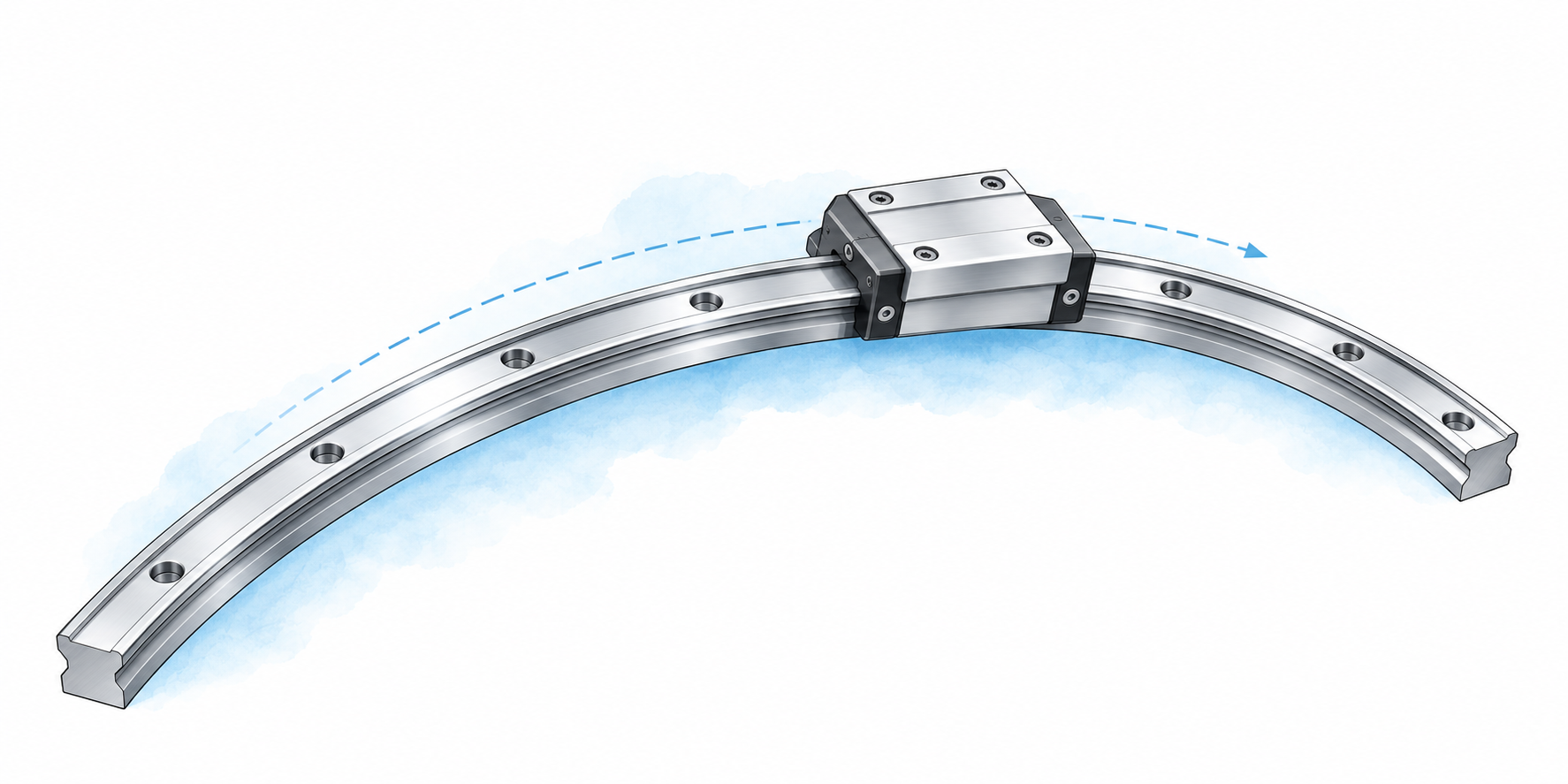
A practical guide to curved linear guide systems: how curved guide rails work, how to plan radius and arc layout, how curved sections redistribute carriage load, and when straight rails with rotary joints are the better choice.
Curved Linear Guide Selection: Radius and Design Rules
A curved linear guide carries a carriage along an arc rather than a straight line. The rail itself is formed to a profile radius, and the carriage runs through the profile with rolling elements or a sliding interface between them. That single geometric change is what makes curved guide rails useful for transfer tables, indexing stations, pallet return loops and other paths that must turn without stopping to reorient the load.
The selection problem is not simply finding a rail that bends. A curved section changes how load reaches the carriage, how many carriages the arc needs and how the motion is driven. Radius, carriage count, speed and load all interact, and each must be checked against the manufacturer rating for the specific rail, not inferred from a catalog headline.
Key takeaways
- A curved guide is a profiled rail formed to a radius with carriages running along the arc.
- Curved sections redistribute carriage load and introduce side loading that a straight rail does not see.
- Radius and arc layout are decided together with load, speed and duty cycle, not independently.
- When the path is straight, standard profile guideways remain the simpler and better-supported route.
- Any value used for radius, speed, load or travel life must be confirmed against the datasheet.
What a curved guide system contains
A curved linear guide is a system, not a single part. Understanding the components helps when specifying the arc and judging what a supplier can actually offer.
- The curved rail. A profiled rail machined or formed to a radius, usually with a mounting base that follows the arc and fixing holes placed along the curve.
- Carriages. Bearing or sliding blocks sized to the rail profile, each with a load rating for radial, side and moment directions.
- The arc support structure. The frame, plate or ring that locates the rail and holds its radius during operation; the rail cannot hold its own curve under load.
- The drive and transmission. Pinion and ring gear, a curved timing belt path, a rotating arm or another method suited to moving along an arc.
- Lubrication and protection. Grease points, wipers or covers appropriate to the arc and the environment.
Because the rail is curved, the fixing pattern and the joint between rail sections matter as much as the profile size. A rail that is supplied in segments must be aligned so the carriage crosses each joint without a step. Ask how the supplier handles joints, fixing positions and the radius tolerance, and check those answers against the drawings you intend to release.
Planning the radius and the arc layout
Radius is the first design variable because it sets the geometry of everything else: the length of rail needed, the fixing density, the sweep angle and the space occupied by the structure. Two arcs with the same sweep angle but different radii are not interchangeable, and two arcs with the same radius but different sweep angles are not either.
Plan the arc as a set of decisions rather than a single number:
- Path length and sweep. Decide how far the carriage travels and how far it turns. A larger sweep spreads fixing holes over more rail and changes the joint layout.
- Available envelope. The outer radius must clear the frame, drive and surrounding equipment; the inner radius must clear the hub, rotating parts or the load itself.
- Mounting orientation. A rail mounted face-up, face-down or on its side loads the carriage differently. Decide the orientation before selecting a profile size.
- Rail segmentation. If the arc needs more than one rail piece, define where the joints fall and how they will be aligned.
- Drive compatibility. The chosen drive must match the arc length and sweep; a pinion or belt path sized for a straight run will not necessarily suit a curve.
Where the arc meets a straight section, plan the transition as its own detail. The carriage must pass from the curved rail to the straight rail without a change in height or a step at the joint. Treat the transition as a precision joint with its own tolerance, not as a place where two rails happen to meet.
No single radius value is universally correct. The usable radius range, the minimum bending radius and the profile sizes available are manufacturer-specific, so confirm against the datasheet rather than copying a figure from another project.
How curved sections change carriage load distribution
On a straight rail, the carriage carries radial load and moment as the rail profile allows, and the load direction stays roughly fixed relative to the carriage. On a curved rail, the carriage is constrained around an arc, so the interaction between load direction and the rail profile changes along the path. Several effects follow from that:
- Side loading appears. Because the carriage is following a curve, load can act against the side of the profile in ways a straight guide does not experience. Carriage ratings for side load and moment therefore become part of the selection, not an afterthought.
- Load shifts between carriages. When several carriages share an arc, the distribution of load among them depends on where each carriage sits along the curve and how the driven element pushes on them. A carriage near the end of the arc is not necessarily loaded like one mid-arc.
- Moment grows with the arm. If the load sits on an arm extending from the carriage, the moment arm about the carriage changes as the carriage travels around the radius. That has to be checked across the whole arc, not only at the start position.
- Speed and acceleration add to the check. The dynamic contribution to load depends on the speed profile and the duty cycle. A rail that looks adequate under static load may not be adequate once acceleration is included.
The practical consequence is that a curved guide cannot be selected with the static load list alone. Ask the supplier for the carriage ratings in the directions you will use, then check them against the load and moment envelope at the worst point of the arc. Confirm all rating values against the datasheet; the selection method matters as much as the numbers.
Curved guide or straight rails with rotary joints?
The choice between a curved linear guide and a combination of straight rails and a rotary joint is a question of path geometry. When a load must turn continuously along an arc with one carriage following a single rail, a curved guide matches that path directly. When the path is essentially a straight run that happens to rotate at one point, a rotary joint with straight rail approach sections may describe the motion more simply.
| Consideration | Curved linear guide | Straight rails with rotary joint |
|---|---|---|
| Path shape | Continuous arc on a single formed rail | Straight approach, rotation at a defined point |
| Carriage load character | Side load and moment along the arc must be checked | Load direction tied to the straight sections and the joint |
| Number of transitions | Any joint between curved and straight rail adds a precision step | The rotary joint becomes the critical transition |
| Drive layout | Drive must follow the arc | Drive acts on the rotating element |
| When it fits | The path is genuinely curved | The path is straight with a single reorientation |
A curved guide earns its place when the motion really is an arc and the load can be carried along it. Replacing that with straight rails plus a rotary joint may mean the load changes direction at a point rather than following the path, which can change the motion and the structure. Conversely, forcing a curved rail into a path that could be a straight run adds side loading, joint tolerance and drive complexity for no benefit. If the path is straight, standard profile guideways apply instead; there is no need to introduce a curve.
Honest limits of curved guides
Curved guides are the right tool for curved paths, and they are also a more demanding tool than a straight profile rail. Knowing the limits early prevents specifying a curve that cannot be delivered or maintained.
- Radius range is finite. Rail profiles have limits on how tight a radius they can hold, and the usable range depends on the profile size. Confirm against the datasheet.
- Joints are critical. Any segmented rail or curved-to-straight transition must be aligned so the carriage does not step. The alignment tolerance is part of the specification.
- Deflection changes the radius. Frame stiffness, rail support and load interact. A flexible base makes the effective radius vary along the path.
- Maintenance access is reduced. Lubrication points and wipers may be harder to reach around an arc than along a straight rail.
- Side load and moment dominate selection. The carriage is not rated on radial load alone, and the worst load position on the arc must be found.
- Speed and duty cycle matter. The dynamic load depends on the speed profile and how often the path runs. Confirm the applicable speed and duty cycle limits with the manufacturer.
None of these limits makes curved guides unsuitable. They make the selection precise. A design that accounts for radius, arc support, carriage load distribution and joint alignment is a design that will run; one that treats a curved rail as a bent version of a straight rail is not.
Practical selection steps
Define the motion first
Write down the path: the start and end position, the sweep, the load carried, the speed profile and how often the motion repeats. This is the input to every later decision, including whether a curved rail is the right answer at all.
Fix the arc and radius
Choose the radius that fits the envelope and the drive, then check it against the available rail profiles and their usable radius range. Confirm against the datasheet before fixing the drawing.
Check carriage load along the arc
Identify the worst position on the arc for side load, radial load and moment, including the dynamic contribution from the speed profile. Compare those values with the carriage ratings in the directions you will use.
Resolve joints and support
Decide where rail segments join and how the transition to any straight section is made. Specify the stiffness and alignment of the arc support, because the rail follows the structure.
Confirm the drive and maintenance
Match the drive to the arc and check that lubrication points and wipers remain accessible. Confirm the speed and duty cycle limits with the manufacturer.
Specifying a curved guide for a quotation
A curved linear guide requirement is easier to answer when the arc, the load and the environment are on one drawing. A specification that a supplier can work from normally includes the radius and sweep, the mounting orientation, the rail profile size or the load it must carry, the carriage count and spacing, the expected load and moment directions, the speed profile and duty cycle, the environment and any protection needed, and the joint and transition positions. Where a value is not yet fixed, say so and state the constraint that limits it, rather than leaving the supplier to guess.
The curved guide rail is a real solution for curved transfer paths; it is not a universal upgrade. Use the radius, layout, carriage load and joint checks to decide whether the path suits a curved rail, plan the arc as a joint design rather than a single dimension, and compare the result with the straight-rail alternative before committing. Any radius, speed, load or travel life figure you rely on should be confirmed against the datasheet for the rail and carriage you intend to use.