
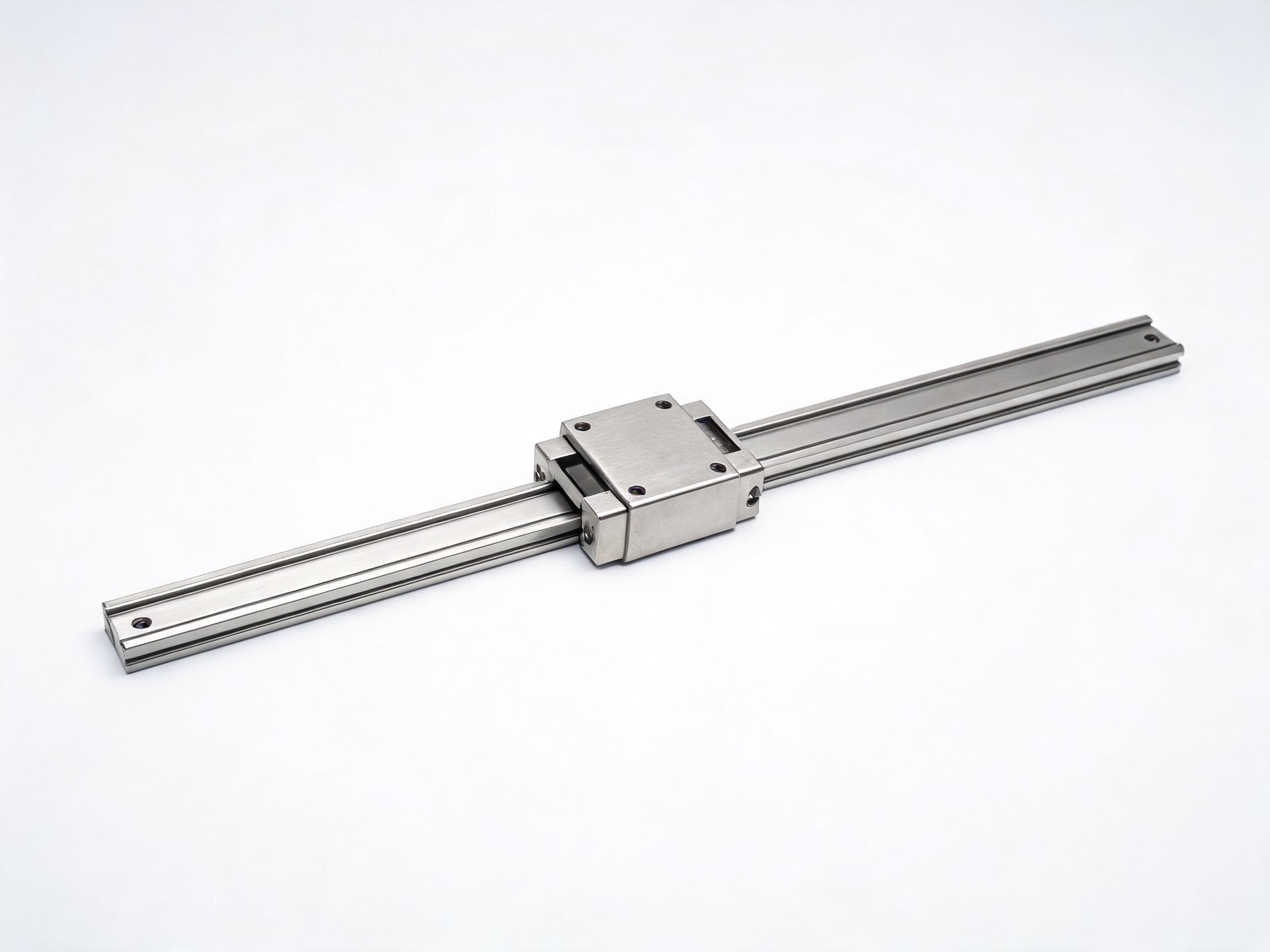
Running an axis faster does not simply require a bigger motor. Speed shifts the balance between preload drag, ball-circuit friction, heat, lubrication intervals, and vibration, so the specification that suits a heavy cutting machine is rarely the one that suits a fast transfer axis. This article explains what actually limits speed in a guide system, how preload grades and ball-circuit geometry trade rigidity against running smoothness, when miniature two-row circuits win, and how to plan lubrication for continuous duty on high-speed linear guide rails.
Selection Guide for High-Speed Duty
Speeding up an axis is rarely a matter of selecting a faster motor. Once travel speed rises, the limiting factors inside a linear guide system change: friction turns into heat, preload turns into drag, and lubrication intervals start to be measured in kilometers of travel rather than calendar months. This article explains what actually limits speed, which specifications you should reconsider as velocity climbs, and how to plan lubrication for continuous high-speed duty.
Key Takeaways
- Friction, preload drag, heat, lubrication film life, and vibration — not nominal speed ratings — set the practical ceiling of a fast axis.
- Preload grade is a direct trade-off: C1 carries most CNC axes, C0 zero clearance suits high-speed linear transfer systems where noise is a concern, and C2 is for heavy cutting rather than fast running.
- A two-row Gothic-arch circuit such as the EGH series runs with roughly 30 percent lower friction than a comparable four-row carriage at equivalent speeds, which lowers both heat and motor torque demand.
- For miniature, stepper-driven axes, a friction coefficient of 0.002–0.004 (MGN series) reduces the torque the motor must supply.
- On HGH-series carriages, the lithium grease reference is NLGI 2 with re-greasing every 100 km of travel or every 3 months, whichever comes first.
In this article
- What actually limits speed in a guide system
- Specifications that trade rigidity against running smoothness
- Preload grades: which one for which duty
- Ball-circuit geometry and friction
- When miniature two-row circuits win
- Lubrication planning for continuous duty
- FAQ
What Actually Limits Speed in a Guide System
When an axis runs slowly, the guide system is mostly a positioning device: stiffness dominates the design decision, and almost any preload grade feels acceptable. At higher speeds, four mechanisms start to matter more than nominal load capacity.
- Friction heat. Every rolling contact in the ball circuit converts a fraction of the motion into heat. At low speed the heat dissipates quietly; at high speed, with reversing cycles, the carriage and rail can warm up enough to affect preload and lubrication.
- Preload drag. Preload is created by slightly oversizing the balls relative to the raceway gap. That same interference that gives rigidity also gives drag, and drag scales with distance traveled per unit time. High preload plus high speed equals continuous mechanical resistance.
- Lubrication film life. Grease is not consumed by time alone; it is worked and displaced by travel. A fast axis passes many more ball circuits per hour, so grease redistribution and replenishment become the controlling maintenance task.
- Vibration and running smoothness. At speed, minor geometric inconsistencies — ball-to-ball spacing, raceway finish, entry and exit transitions — become audible and measurable. Smooth running is a separate specification from load capacity.
In other words, a high-speed linear guide is not simply a stronger guide. It is a guide whose friction, preload, and lubrication characteristics have been chosen for a different operating regime.
Specifications That Trade Rigidity Against Running Smoothness
Machine builders often ask for the stiffest guide available and then discover the axis runs hot, loud, and with a large motor. Rigidity and smoothness pull in opposite directions, and speed changes which side of that trade-off you should sit on.
| Specification | Bias toward rigidity | Bias toward smooth, fast running |
|---|---|---|
| Preload grade | Higher preload (C2 medium) | Lower preload (C0 zero clearance, C1 light) |
| Ball circuit | Four-row, maximum contact | Two-row Gothic-arch, lower friction |
| Raceway finish | Typically coarser | Ra 0.4 µm or finer on the EGH series |
| Friction level | Higher — more drag per stroke | Lower — less heat per stroke |
| Running noise | Not a design priority | 48 dB or less at 0.5 m/s on the EGH series |
The right column is not "better" in general terms. It is the correct set of choices when the axis spends most of its time moving rather than cutting under heavy load. A heavy-cutting machine needs the left column; a fast transfer or pick-and-place axis usually needs the right one.
Preload Grades: Which One for Which Duty
Preload is the single specification most often left unchanged when an axis is sped up, and it is the one that most directly determines how much heat the carriage generates. The HGH preload grades are intended for clearly different duties:
- C0 — zero clearance. Suited to high-speed linear transfer systems where noise is a concern. With no interference fit beyond clearance removal, drag stays low and the axis runs quietly.
- C1 — light preload. The default choice for most CNC axes. It provides enough rigidity for accurate positioning without the drag penalty that heavier preloads impose.
- C2 — medium preload. Intended for heavy cutting, where the cutting force and the need for rigidity outweigh friction considerations.
A common specification error is to upgrade a fast transfer axis to C2 "for accuracy" and then fight heat, noise, and motor sizing. If the process loads are light and the axis travels quickly, C0 or C1 is usually the more appropriate starting point; heavy cutting is where C2 earns its place.
Ball-Circuit Geometry and Friction
The number of ball rows and the shape of the raceway govern how much contact area carries the load — and how much friction is produced while doing so. A four-row carriage distributes load across more contact points; a two-row Gothic-arch circuit concentrates contact differently, and in the EGH series that geometry runs at approximately 30 percent lower friction than a comparable four-row carriage at equivalent speeds.
Lower friction has three practical consequences on a high-speed axis. Less energy is converted to heat, so thermal growth and preload drift are reduced. Motor torque demand falls, which can allow a smaller motor or a higher acceleration margin. And running noise drops: the EGH series is specified at 48 dB or less at 0.5 m/s, with raceway surface roughness of Ra 0.4 µm or less. For machines installed in clean rooms, laboratories, or shared production floors, that noise figure is often a selection criterion in its own right.
For heavy-duty structures, the HGR series heavy-duty linear guideway rail provides a matched rail platform, and the HGR rail profile includes an oil groove that retains a lubricant film between re-greasing intervals — useful when a fast axis would otherwise push grease away from the contact zone.
When Miniature Two-Row Circuits Win
Miniature axes driven by stepper motors are a distinct case. Motor torque is limited, and any friction in the guide directly reduces the acceleration the axis can achieve or increases the risk of missed steps. The MGN series addresses this with a friction coefficient of 0.002–0.004, which keeps the torque required from the stepper low enough for compact drives.
These miniature two-row circuits win when three conditions apply at once:
- The moving mass and payload are small, so the lower load capacity of a miniature carriage is not the limiting factor.
- The axis cycles frequently, so accumulated friction heat and motor heating matter more than peak stiffness.
- The machine envelope is tight, so a smaller carriage and rail height are required.
Where the payload or cutting force is large, the miniature platform is the wrong starting point regardless of speed; the HGH series flange-type linear guideway carriage block and its HGR rail remain the structural choice, with preload selected according to cutting duty.
Lubrication Planning for Continuous Duty
On a slow axis, lubrication is a calendar task. On a fast axis, it is a travel-distance task, because the ball circuit works the grease at a rate proportional to distance covered.
For HGH-series carriages, the reference schedule is lithium grease NLGI 2, with re-greasing every 100 km of travel or every 3 months, whichever comes first. The carriage uses an M6 grease nipple. Two planning points follow from that:
- Convert the interval into machine terms. If a single shift covers a known distance, the 100 km figure translates directly into a number of shifts or days, which is what maintenance planning actually needs.
- Treat "whichever comes first" literally. A machine that runs fast but only occasionally may reach three months before 100 km; a machine on continuous duty may reach 100 km in a fraction of that time, especially with short, reversing strokes.
Where a carriage is available in a two-row configuration, the EGH series miniature linear guideway rail and carriage combines the low-friction circuit with the rail surface finish noted above, which is relevant when the lubrication film must survive high cycle counts.
FAQ
Can linear guides run fast?
Yes, but what changes is not a single speed number — it is the specification set. A guide selected for fast running needs friction and preload appropriate to continuous motion, a lubrication interval expressed in travel distance, and a raceway finish that keeps noise and vibration low. The relevant limits come from friction heat, preload drag, lubrication film life, and vibration, not from a single catalog rating.
What preload should I choose for high speed?
For high-speed linear transfer systems where noise is a concern, C0 zero clearance is the appropriate grade. For general CNC axes, C1 light preload is the usual choice, since it delivers positioning rigidity without excessive drag. C2 medium preload is intended for heavy cutting rather than high-speed duty, and using it on a fast axis generally increases friction heat and motor load. Confirm the final grade against the actual process loads and duty cycle with the guide supplier.
Does a lower-friction circuit reduce motor size?
It reduces the friction component of the torque the motor must supply, which can allow a smaller motor or more acceleration margin at the same motor size. The EGH two-row Gothic-arch circuit runs at approximately 30 percent lower friction than a comparable four-row carriage at equivalent speeds. The total torque requirement still depends on the moving mass, acceleration profile, and external loads, so motor sizing should be checked against the full axis calculation.