
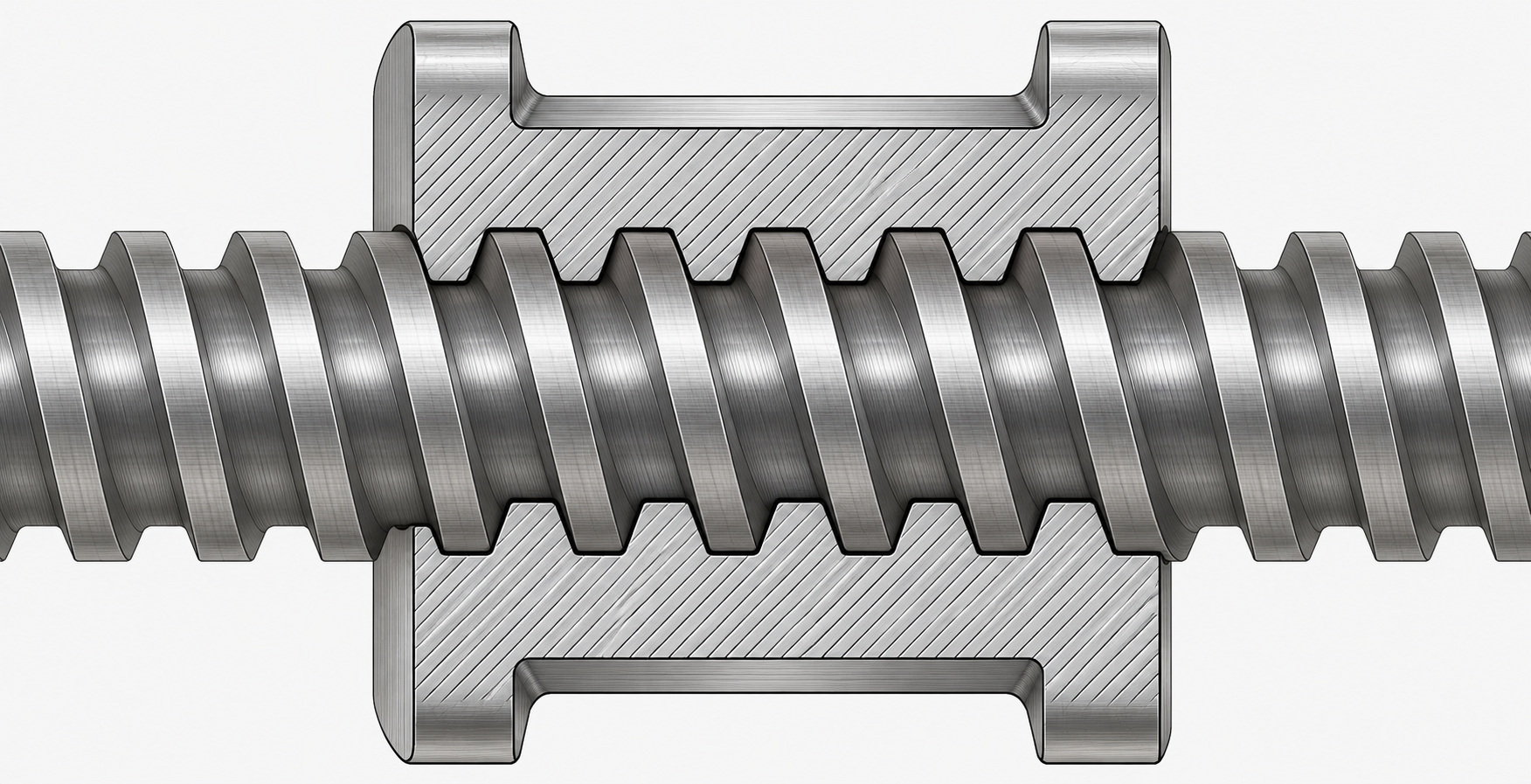
A lead screw and nut assembly turns rotation into linear motion through sliding thread friction. This guide explains the working principle, the common nut types and mounting styles, the self-locking trade-off, and when a rolling-contact ball screw is the better choice for positioning work.
Lead Screw and Nut Assembly: How It Works and How to Choose

A lead screw and nut assembly converts rotary input into linear motion through sliding thread friction. The screw carries an external thread; the nut carries a matching internal thread. When the screw rotates and the nut is restrained from turning, the nut travels along the screw axis. Because the two threads slide against each other rather than roll, the assembly is simple in construction and, at typical lead angles, can hold a position without a brake. Those two properties drive most specification decisions. This guide explains the mechanism, the nut styles and mounting arrangements you will encounter, the self-locking trade-off, and where a rolling-contact ball screw becomes the better choice.
- A lead screw transmits motion through sliding friction between screw and nut threads, not through rolling elements.
- Nut styles include flange and cylindrical types, and each has different mounting implications.
- At typical lead angles, lead screws can be self-locking; ball screws are not inherently self-locking.
- Ball screws use recirculating balls in rolling contact for higher efficiency, precision, and speed capability.
- Diameters, pitches, efficiencies, materials, and load ratings are not fixed by category; confirm every value against the datasheet for the specific assembly.
The sliding-friction working principle
In a lead screw and nut assembly, the screw and nut threads remain in direct sliding contact. Rotation of the screw forces the nut to move axially because the thread flanks push against each other. The thread profile is commonly trapezoidal, which provides a robust flank for sliding contact and is widely used in motion-transfer applications. The exact profile, material pairing, and surface treatment belong to the specific assembly and must be confirmed against the datasheet. The practical consequence of sliding contact is that friction is present by design. That friction consumes torque and generates heat, so the efficiency of a sliding lead screw is lower than that of a rolling element screw. It also produces the self-locking behavior discussed below. A lead screw assembly is therefore well suited to applications where the load is moderate, the motion is intermittent, and the simplicity of a non-recirculating nut is an advantage. Where continuous high-speed operation or very low drive torque is required, the friction loss becomes the limiting factor, and a rolling-contact alternative should be evaluated.
Nut types and mounting styles
The nut is where the assembly connects to the moving member, and its shape determines how that connection is made. Two broad families dominate: flange nuts and cylindrical nuts. Flange nuts carry a mounting flange, usually with bolt holes, so the nut can be bolted directly to a carriage, bracket, or plate. The flange provides a stable mounting face and simplifies alignment during assembly, because the nut is fastened at several points rather than gripped in a housing. Cylindrical nuts present a plain outside diameter that is held in a housing, clamp, or pillow block. The housing then carries the mounting interface. Cylindrical nuts can suit designs where the nut must sit inside a bore or where radial space is tight, but the housing itself becomes part of the alignment chain.
Mounting style matters beyond the nut shape. The screw is normally supported at one or both ends by bearings, and the choice of support affects axial stiffness and permissible speed. A nut that is bolted through a flange transfers load through its bolt pattern; a nut held in a housing transfers load through the housing interface. In either case, the mounting must keep the nut from rotating while allowing it to travel, and it must not impose bending on the screw. The practical rule is to define the moving member first, then select the nut style that matches its mounting surface. Confirm the flange dimensions, bolt pattern, and housing bore against the datasheet before committing to a drawing.
Self-locking: the trade-off
At typical lead angles, a lead screw can be self-locking. In simple terms, the friction angle of the sliding thread is large enough relative to the lead angle that an axial load on the nut does not drive the screw backward. The nut stays where it is put when the drive is removed. That is valuable in applications such as lifting, clamping, or vertical positioning, where a power-off condition should not let the load run back down. The same friction that produces self-locking also produces lower efficiency and higher drive torque. The two effects come from one cause and cannot be separated: a screw chosen for reliable self-locking will demand more torque and dissipate more heat than a rolling screw of comparable size. The self-locking condition is also a function of the specific lead angle and friction pair, so it cannot be assumed from the thread type alone. Whether a particular assembly is self-locking under your load must be confirmed against the datasheet and the supplier's engineering data. A ball screw, by contrast, uses recirculating balls in rolling contact and is not inherently self-locking; where holding is required, a brake or a self-locking stage must be added to the drive train.
Lead screw vs ball screw: a specification comparison
The table below compares the two architectures on the characteristics that most often decide the choice. It is qualitative; no efficiency percentage, load rating, or speed limit is stated here, because those values depend on the specific assembly and must be read from the datasheet.
| Characteristic | Lead screw and nut assembly | Ball screw assembly |
|---|---|---|
| Motion transfer | Sliding thread friction between screw and nut | Recirculating balls in rolling contact |
| Self-locking | Can be self-locking at typical lead angles | Not inherently self-locking |
| Efficiency | Lower, due to sliding friction | Higher, due to rolling contact |
| Precision and speed capability | Suited to moderate precision and speed | Higher precision and speed capability |
| Nut styles | Flange and cylindrical types | Flange and cylindrical ball nut types |
| Holding on power-off | May hold via self-locking, depending on lead angle | Requires a brake or self-locking drive stage |
The comparison is not a verdict. A lead screw wins where simplicity, self-locking, and cost-effective motion transfer dominate. A ball screw wins where efficiency, precision, and speed capability dominate. The decision should follow from the duty cycle and the required positioning accuracy, not from a general preference for one architecture.
When a lead screw is sufficient and when a ball screw is the better choice
A lead screw and nut assembly is sufficient when the application tolerates sliding friction and does not demand high efficiency or high speed. Typical conditions include intermittent adjustment, manual or low-duty actuation, vertical motion that should hold when power is removed, and designs where a simple nut without a ball recirculation path is preferred. In these cases the self-locking behavior is an asset rather than a compromise.
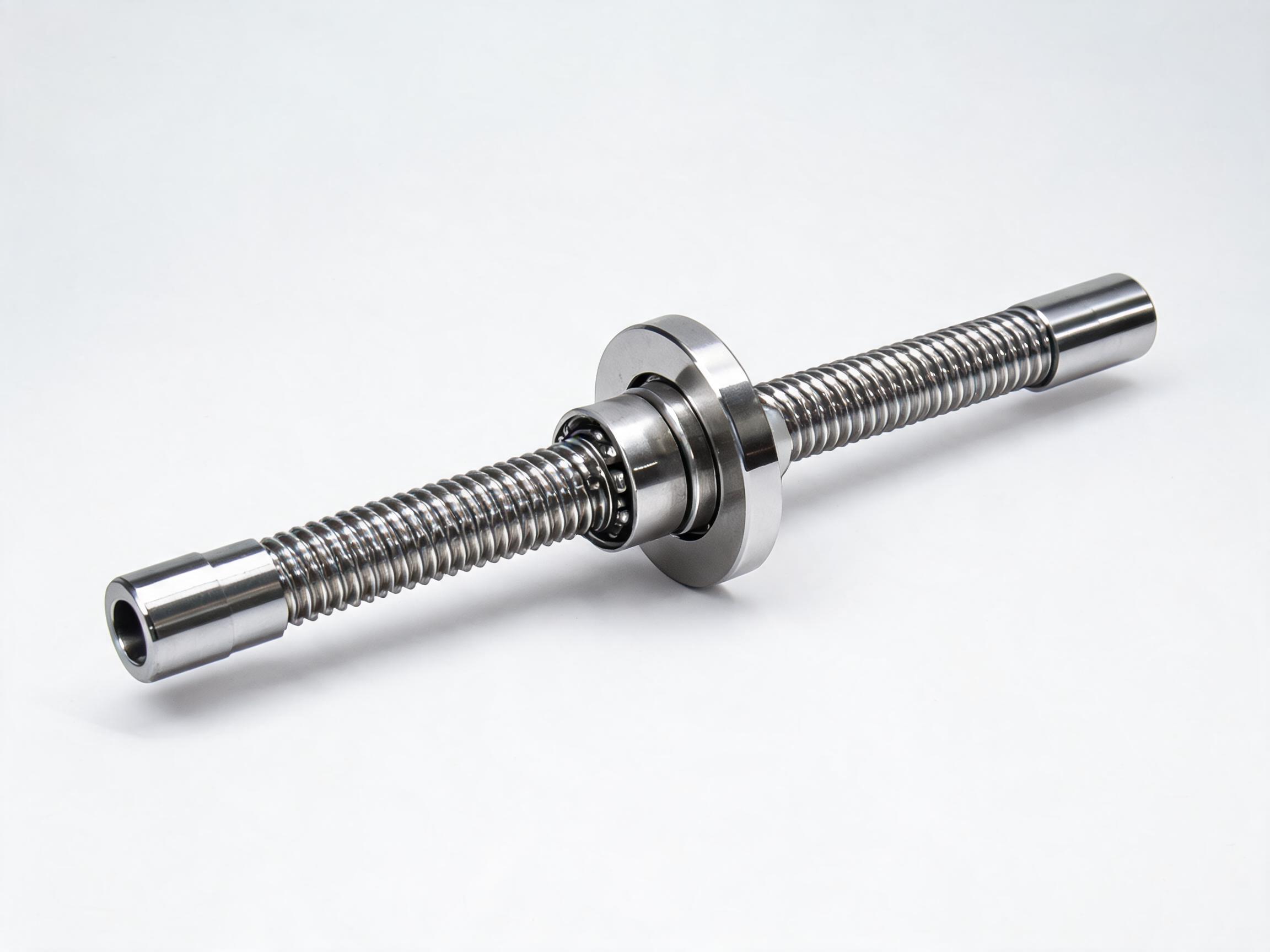
A ball screw is the better choice when the application requires higher efficiency, higher precision, and higher speed capability than a sliding screw can provide. Continuous motion, accurate positioning, and low drive torque all point toward rolling contact. The trade-off is that a ball screw is not inherently self-locking, so a holding function must be designed into the drive. Our rolled ball screw assemblies are built on this rolling-contact principle. The SFU series rolled ball screw assembly covers the general range, and the SFU2510 rolled ball screw assembly with flange nut is a specific example of the flange-nut configuration. These are offered as the rolling-contact alternative where a lead screw's friction losses or lack of precision would limit the design; they are not lead screw products, and their specifications should be read from their own datasheets.
Specifying a lead screw and nut assembly
Once the architecture is chosen, the specification work is about matching the assembly to the load, the motion, and the mounting. The following checklist covers the points that most often cause a mismatch. None of these values can be assumed from the category; each must be confirmed against the datasheet for the specific assembly under consideration.
- Load and duty cycle. Define the axial load, the direction of loading, and whether the motion is intermittent or continuous. These determine whether sliding friction is acceptable.
- Self-locking requirement. State whether the nut must hold position when the drive is removed. If yes, the lead angle and friction pair must be checked for self-locking under your load.
- Nut style and mounting. Choose flange or cylindrical based on the moving member's mounting surface. Confirm flange dimensions, bolt pattern, and housing bore against the datasheet.
- Screw support. Decide the bearing arrangement at each end of the screw and confirm that the mounting does not impose bending on the screw.
- Precision and speed. State the required positioning accuracy and travel speed. If these exceed what sliding contact can deliver, revisit the ball screw alternative.
- Environment. Confirm the material and surface treatment against the datasheet where corrosion, temperature, or contamination is a factor.
The final step is to reconcile the drawing with the datasheet. A lead screw and nut assembly is a system: screw, nut, and mounting interact. A change in nut style or screw support can change the stiffness and the self-locking behavior of the whole arrangement. Confirm every unverified parameter against the datasheet before releasing the design, and where the application demands rolling contact, specify a ball screw assembly from its own documented data.