
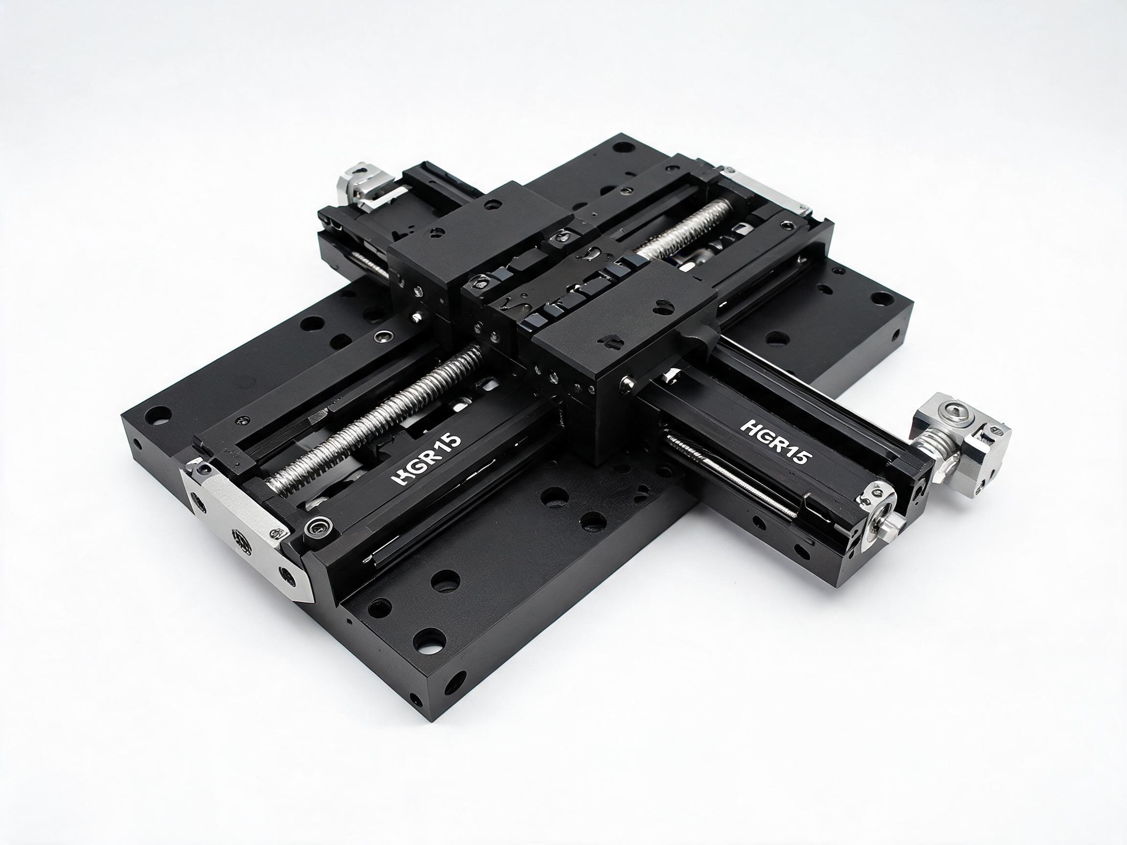
Three practical ways to add linear motion to 80/20-style T-slot aluminum extrusion: carriage wheels in the groove, a bolted-on profile guide rail, and an integrated slide module. Covers load, repeatability, duty cycle, and drive integration, with the SKF20 module as a worked example.
Linear Motion on T-Slot Extrusion
If you are building a gantry, a test fixture, or a small pick-and-place axis on 80/20-style T-slot aluminum extrusion, there is no single right answer for the linear bearing. There are three, and the correct one depends on what the axis has to do. Groove-riding carriage wheels are the cheapest way to get a moving platen on an extrusion frame, and they are fine when the motion is light, slow, and forgiving. When an axis needs repeatability, load capacity, or a defined service life, the usual upgrade is to bolt a hardened profile guide rail and a recirculating carriage onto the same extrusion. When you would rather not design the rail, carriage, screw, and motor interface yourself, an integrated slide module combines all of them on one extrusion-based base.
This article compares those three routes under the same conditions and lays out the decision criteria — load, repeatability, duty cycle, and drive integration — that separate them in practice. It also walks through the SKF20 module as a worked example of the integrated approach.
Key Takeaways
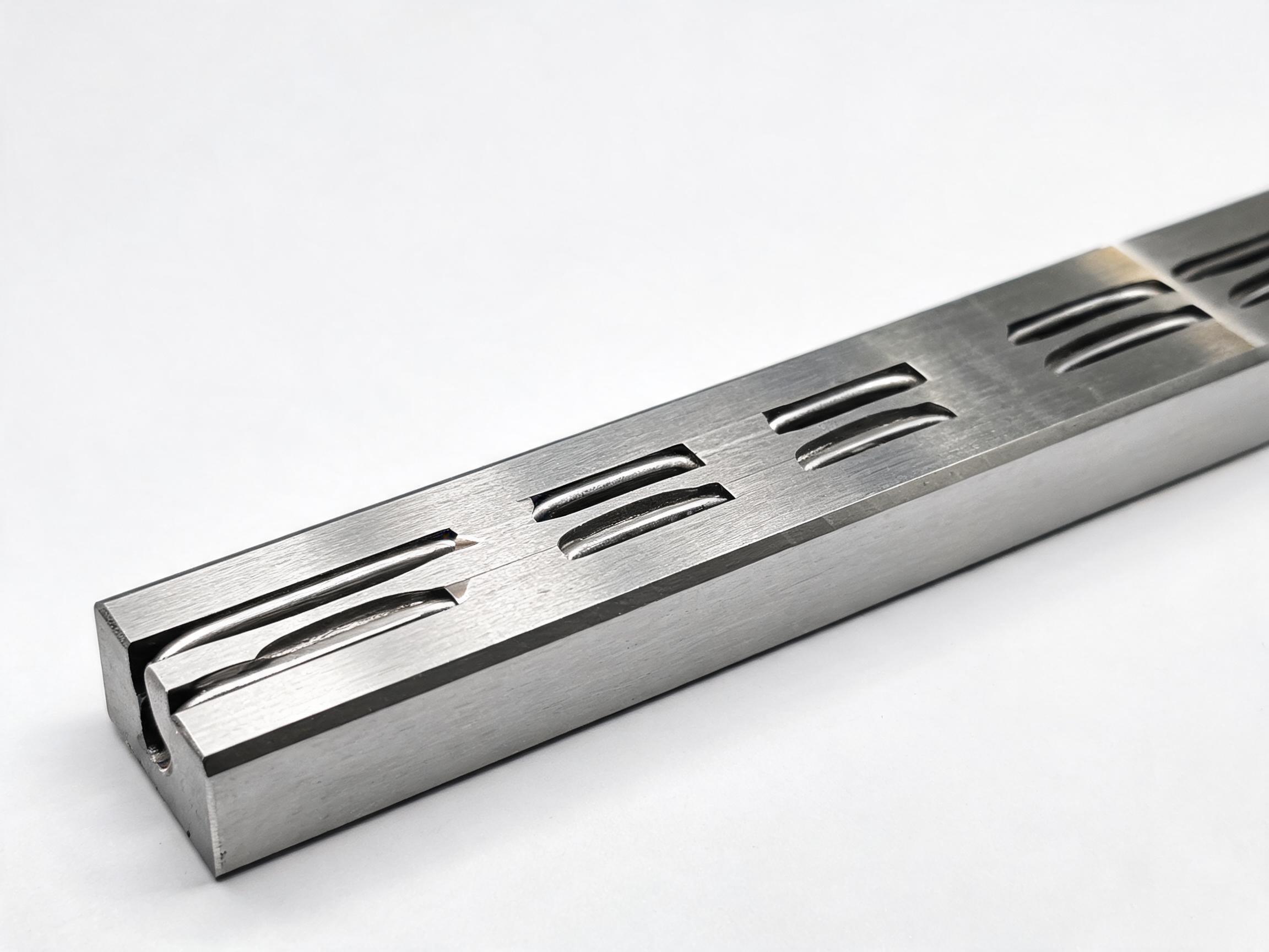
- Extrusion-groove carriage wheels buy low cost and simple mounting; they do not buy precision or long wear life.
- A separate profile rail and carriage bolted to the extrusion moves load capacity and repeatability onto a hardened steel interface.
- An integrated slide module packages rail, carriage, ball screw, and motor mount on one base, removing most of the mechanical design work.
- The four criteria that actually decide the route: load, repeatability, duty cycle, and drive integration.
In this article
Option 1: Carriage wheels in the extrusion groove
This is what most people mean when they search for an "80/20 linear bearing." A carriage plate carries a set of wheels whose profile matches the T-slot groove; the wheels roll directly in the extrusion, and the extrusion itself is the raceway. The rails are the frame members you were already buying.
The appeal is obvious. There is no additional rail to procure, no rail mounting surface to machine flat, and almost nothing to align at assembly. For a light shuttle, a sliding door panel, a manual adjustment stage, or a low-speed positioning fixture, this is a workable and inexpensive design.
The trade-offs are equally clear. The groove of a general-purpose T-slot extrusion is not a bearing raceway; it is a structural and mounting feature. Wheel-based motion therefore accepts looser guidance than a profile rail, and the contact between a polymer or small steel wheel and an anodized aluminum groove is a wear surface. Over thousands of cycles, that contact can loosen, and the axis can develop play that shows up as lost repeatability. Wheel carriages also tend to offer limited ability to preload out backlash, and they are sensitive to debris in the groove.
Where this route belongs: motion that is light, intermittent, and does not need to return to the same position within a tight band.
Option 2: Bolt-on profile guide rail and carriage
The standard upgrade is to stop using the extrusion as the raceway. Instead, a hardened, ground profile guide rail is mounted onto the extrusion, and a recirculating ball carriage rides on that rail. The extrusion keeps doing what it is good at — acting as the structural frame and the mounting interface — while the rail and carriage take over guidance and load.
The performance difference comes from the hardware. In the HGR series, rail sizes run from HGR15 to HGR45, the rail material is 55# steel that has been induction hardened to 58–62 HRC, and rails can be supplied in lengths up to 4000 mm. Hardened and ground steel running surfaces hold geometry far better than an aluminum groove, and a ball carriage provides rolling contact with preload options that reduce play.
What this route costs you is engineering effort. You have to select a rail size against your load and moment requirements, provide a flat and reasonably parallel mounting surface, align the rail to the frame, and engineer the drive separately — belt, screw, or rack. You also have to design the carriage-to-platen interface. Done well, this is the highest-performance of the three routes and the most flexible, because rail size, rail length, carriage type, and drive are independent choices.
Where this route belongs: axes that need real repeatability, higher load, or a long, defined duty cycle, and where you have the design resources to integrate it.
Option 3: Integrated slide module
A slide module is the third route, and it is the one that answers a different question. Instead of asking you to select a rail, a carriage, a screw, and a motor interface, a module arrives as one assembly built on an extrusion-compatible base. The rail, carriage, drive screw, and motor mounting are already matched to each other and to the base.
The engineering value is not just fewer parts. It is that the alignment between rail and screw has already been done, the mechanics and the drive are dimensioned to work together, and the mounting pattern is fixed. That shortens the design loop and removes several failure modes that come from mismatch between separately sourced components. For machine builders who are integrating several axes and would rather spend engineering time on the machine than on the axis, this is the fastest route from requirement to a specified, wireable unit.
The trade-off is flexibility. You are buying a defined envelope of stroke, load, and drive rather than an open choice of every component. Customization is possible, but it moves along the module's design rather than in any direction you like.
Decision criteria
Four parameters decide the route in most builds.
Load and moment
Estimate not just the payload mass but where it sits relative to the carriage. An offset load creates a moment that a wheel carriage tolerates poorly and that a profile rail and carriage handle by design. If the moving mass is small and centered, wheels can be adequate. If it is heavy or overhanging, the rail and carriage route, or a module, is the realistic choice.
Repeatability
Decide the number before you decide the hardware. If the axis only needs to arrive "about there," wheels may be sufficient. If it must return to the same position consistently, you need the preload and stiffness of a ball carriage on a hardened rail. A module inherits that rail-and-carriage precision but saves you the alignment work.
Duty cycle
Consider the number of cycles per hour, hours per day, and expected machine life together. Groove-riding wheels accumulate wear that eventually shows as play; a hardened steel rail and ball carriage are designed for continuous operation. Cycle count is often the single criterion that pushes a project from wheels to a rail.
Drive integration
Finally, decide who owns the drive. If you already have a screw or belt design, a bolt-on rail gives you the most freedom. If you would rather specify a stroke, a screw lead, and a motor and receive a finished axis, a module removes that work entirely. Motor mount compatibility matters here: the module needs to accept the motor you intend to use.
| Route | Guidance source | Best fit | Main cost of choosing it |
|---|---|---|---|
| Carriage wheels in the groove | Extrusion T-slot profile | Light, slow, intermittent motion; simple shuttles and adjustment stages | Looser guidance and a wear surface that can loosen over many cycles |
| Bolt-on profile rail and carriage | Hardened, ground steel rail | Axes needing repeatability, higher load, and long duty cycles | Rail selection, mounting-surface flatness, alignment, and separate drive design |
| Integrated slide module | Matched rail, carriage, and screw on one base | Builds that want a specified, wireable axis with minimal mechanical design | Less freedom to choose each component independently |
Worked example: the SKF20 slide module
The SKF20 aluminum profile linear motion slide module shows what the integrated route looks like in practice. It is built on a 2020 T-slot aluminum base, and it uses an HGR15 rail with an HGH15CA carriage for guidance. That means the module takes the hardened-steel rail approach from Option 2 and packages it.
The drive is an SFU1605 C7 ball screw with a 5 mm lead, driven through a NEMA17/NEMA23 motor mount. Standard stroke is 100–500 mm, with custom strokes up to 1000 mm. Rated load for the assembly is 11.2 kN dynamic and 17.5 kN static.
Read against the four criteria, the SKF20 answers them directly. Load and moment are handled by the HGR15 rail and HGH15CA carriage rather than by the extrusion groove. Repeatability comes from the ball carriage on a hardened rail. Duty cycle is supported by the same steel-on-steel interface. Drive integration is settled by the 5 mm-lead ball screw and the NEMA17/NEMA23 mount, so you specify a stroke and a motor and the axis is ready to wire.
A 5 mm lead is a fine-pitch choice: each motor revolution produces 5 mm of travel, which suits positioning work where resolution matters more than top speed. If your application needs faster traverse at the same motor speed, that is a sizing conversation to have against the module's stroke and load figures.
If you are working the other way — integrating a rail yourself onto an extrusion frame — the HGR series heavy-duty linear guideway rail is the same family of rail used here, available from HGR15 through HGR45, in 55# steel induction hardened to 58–62 HRC, in lengths to 4000 mm.
A note on the numbers: rated load figures describe the rail and carriage assembly's capacity. Whether a given build stays inside that rating depends on the actual payload, its position relative to the carriage, and the acceleration profile of the axis. Size the axis against your real moving mass and duty cycle, not against the catalog maximum alone.
FAQ
Can I use an extrusion groove as the bearing raceway?
Yes, and many builds do. Carriage wheels running directly in the T-slot are a valid, low-cost approach for light and intermittent motion. The limit is that the groove is an extrusion feature, not a ground bearing surface, so guidance is looser and the contact is a wear surface.
When should I switch from wheels to a profile rail?
When you need defined repeatability, higher load capacity, or a long duty cycle. Cycle count is often the deciding factor, because wheel-based guidance accumulates wear that eventually appears as play.
Why choose a module instead of buying the rail and screw separately?
Because the alignment between rail, carriage, and screw is already done, the parts are matched, and the mounting pattern is fixed. That removes design and assembly steps, at the cost of less freedom to pick each component independently.
What stroke lengths are available on the SKF20?
Standard stroke is 100–500 mm, with custom strokes up to 1000 mm. Confirm your required stroke, payload, and motor when requesting a specification.
Which motor does the SKF20 accept?
It provides a NEMA17/NEMA23 motor mount. Confirm the specific motor frame and shaft details against the module's mount before ordering.
Before you specify
- Moving mass and where it sits relative to the carriage
- Required repeatability at the working position
- Cycles per hour, hours per day, and expected service life
- Whether you are supplying the drive design or buying it integrated
- Stroke, and the motor frame you intend to use
If you have those five inputs, the route usually picks itself: wheels for light and forgiving motion, a bolt-on rail when you control the drive design and need the performance, and an integrated module when you want a specified, wireable axis without the mechanical integration work.