
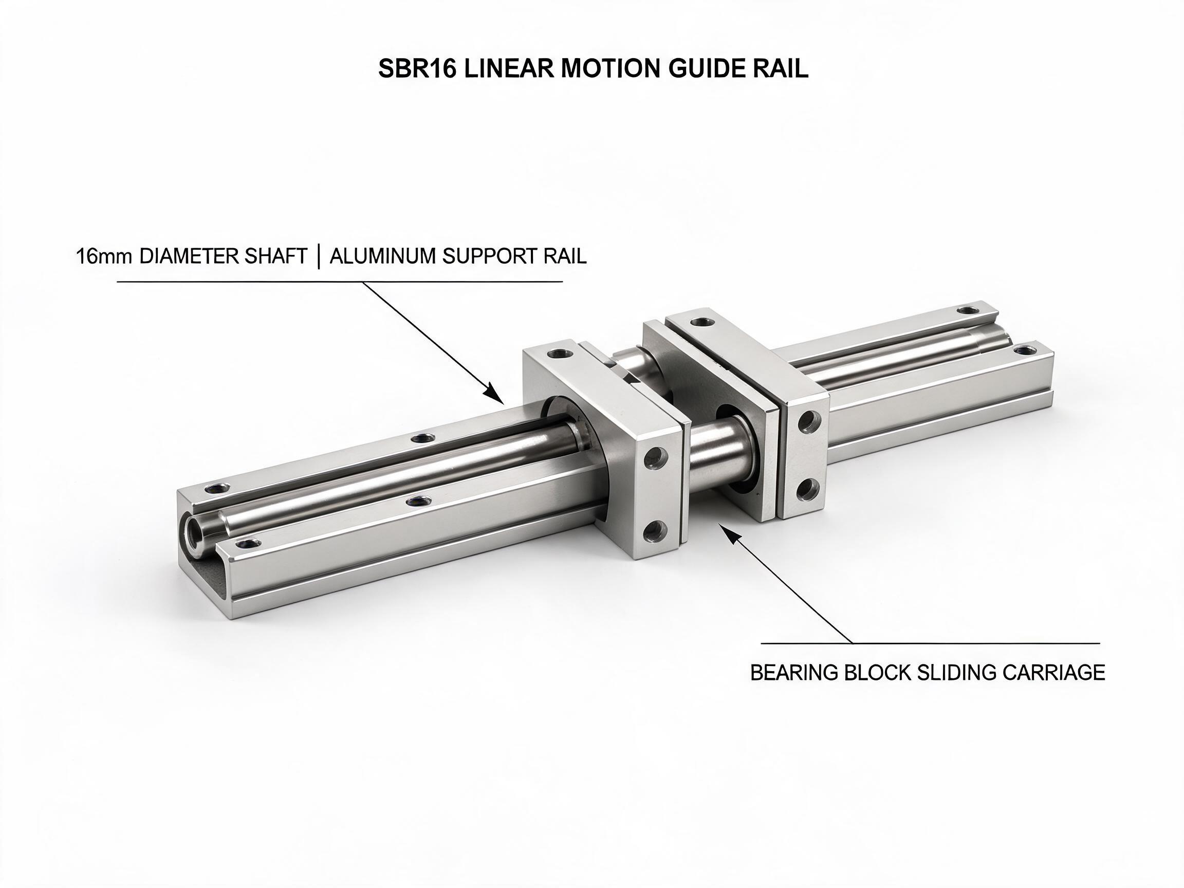
A sizing guide for machine builders buying integrated linear bearing slide rails. Work from load per block, block count and spacing, shaft diameter, and then decide whether an integrated unit, bare shaft with pillow blocks, or profile rails fits the axis you are ordering.
Spec-to-Order Guide
An integrated linear bearing slide rail unit bundles a hardened shaft, an aluminum support rail and one or more ball bearing blocks into a single part number. That simplifies the bill of materials, but it does not simplify the sizing decision. The unit you order has to match a load figure, a block layout and a shaft diameter, and those three inputs are what this guide works through in order.
Key takeaways
- Start from dynamic load per block, not per unit. Two blocks on one axis share the gantry load, so the number the catalog lists per block is the number you divide into the axis load.
- Block count and spacing set the moment capacity. A single block carries a light vertical load fine and resists cantilever moments poorly.
- Integrated slide rail units beat bare shaft with pillow blocks when you want a defined mounting pattern, a supported shaft and a known load rating in one assembly.
- Reach for profile rails when you need internal preload and a low, fully supported carriage travel; reach for round-shaft integrated units when shaft length, mounting simplicity or dust tolerance drive the design.
On this page
- Step 1: convert the axis load into load per block
- Step 2: choose block count and spacing
- Step 3: confirm shaft diameter and length
- Comparing the three SBR and TBR configurations
- When integrated units beat bare shaft or profile rails
- FAQ
Step 1: convert the axis load into load per block
Every catalog rating for these units is stated per block, so the first arithmetic is to decide how much load each block sees. For a horizontal axis with a vertically loaded carriage, the static and dynamic figures divide by block count when the load is evenly distributed. That is the assumption to check, because an offset center of gravity changes it.
The SBR16 linear motion guide rail unit with bearing block is rated for 7.8 kN dynamic and 12.0 kN static per block on a 16 mm shaft. The SBR20 heavy-duty linear motion guide unit with dual bearing blocks is rated 11.2 kN dynamic and 17.5 kN static per block on a 20 mm shaft. Two SBR20 blocks on one axis give 22.4 kN dynamic across the axis.
Those are catalog ratings from the manufacturer. Applied load in a machine includes the gantry, the tool, the workpiece and the acceleration term from the drive. Write the sum down for the heaviest move in the cycle, then divide by block count, then compare against the dynamic figure with a margin you are comfortable defending.
Step 2: choose block count and spacing
Two blocks on one shaft do more than divide the vertical load. They also change the moment the rail has to resist. With two blocks separated along the shaft, the offset load creates a couple that the pair shares; the wider the spacing, the lower the load on each bearing row for the same moment.
The manufacturer's data for the SBR20 states that using dual bearing blocks halves the per-block stress under an equivalent gantry load and extends travel life by about 80% against a single block. That figure is a manufacturer statement for that configuration, not a general life law, but it explains why dual-block units are the standard choice for gantry X and Y axes where the load sits off the shaft centerline.
For a single-block axis, keep the load close to the block center and check the moment rating against the offset distance. A cantilevered Z axis with the load hanging well outside the support is the case where a single 16 mm unit is least comfortable, even if the vertical figure adds up.
Step 3: confirm shaft diameter and length
Shaft diameter follows from the load per block plus the span. A longer span on a small shaft deflects more under the same load, and deflection changes how the load is shared between two blocks. The catalog load values assume the shaft and support rail are mounted on a rigid base at the stated hole pattern.
| Item | SBR16 | SBR20 | TBR16 |
|---|---|---|---|
| Shaft | 16 mm, GCr15, induction hardened HRC 58–62 | 20 mm | Two 16 mm shafts |
| Dynamic load | 7.8 kN per block | 11.2 kN per block; 22.4 kN per axis with two blocks | 15.6 kN per carriage (7.8 kN x 2) |
| Static load | 12.0 kN per block | 17.5 kN per block | 24.0 kN per carriage |
| Support rail | Anodized 6063-T5 aluminum | Aluminum support rail | Two parallel shafts in one system |
| Mounting | Holes every 50 mm; block bolts 4x M5 top face | Confirm with datasheet | Carriage bolts 4x M6 |
| Max standard length | 2000 mm; custom to 4000 mm | 3000 mm | 2000 mm |
| Shaft center distance | — | — | 60 / 80 / 100 mm |
| System height | Confirm with datasheet | Confirm with datasheet | Under 30 mm |
Length is where orders get revised. If your axis runs past the maximum standard length, the SBR16 is listed as custom available to 4000 mm; confirm the lead time and price effect of that length with the supplier before you release the drawing. For any dimension not listed here, such as the SBR20 mounting hole pitch, ask for the datasheet rather than scaling from the SBR16.
Comparing the three SBR and TBR configurations
The TBR16 synchronized dual-shaft linear motion guide system is a different answer to the same problem. Instead of two separate SBR units joined by a plate, it uses two parallel 16 mm shafts and one synchronized carriage in a single housing.
Why synchronization matters for cantilevered axes
Two separate SBR units bolted to a common plate can rotate relative to each other if the plate flexes or the mounting is imperfect. The TBR16 carriage is a single part spanning both shafts, so the manufacturer lists zero yaw versus the two-unit arrangement and twice the moment-load resistance for cantilevered axes. Shaft center distance is 60, 80 or 100 mm, so the moment capacity depends mainly on which of those you order. System height is under 30 mm, which suits a low-profile Z or rotary-support axis.
Choosing between them
If your axis load is moderate and the carriage load is close to the shaft centerline, a single SBR16 unit is the cheapest way to get a supported shaft with a known rating. If the load is heavier or the gantry is long, dual SBR20 blocks give you the per-block sharing and the 22.4 kN axis figure. If the load hangs off the axis or the carriage must stay square against a twisting moment, the TBR16 carriage addresses that directly. Use the load per block calculation for the SBR units and the per-carriage figure for the TBR16 — do not mix the two bases in one comparison.
When integrated units beat bare shaft or profile rails
Bare shaft with separate pillow blocks is a legitimate build. What the integrated unit adds is a hardened shaft already fixed to its aluminum support with a known hole pitch (50 mm on the SBR16), a bearing block sized to that shaft, and a published load rating for the pair. On a machine with a long axis, the support rail matters: an unsupported shaft deflects under load, while the supported shaft in an integrated unit holds its line along the mounting surface. The SBR16 manufacturer figure is about 60% higher dynamic load than single-row LM pillow blocks of the same shaft diameter, which is the comparison to check if you are currently designing around separate blocks.
Profile rails are the right family when you need a carriage with internal preload running on a fully supported track, a low overall height, or a mounting pattern standardized across many carriage sizes. Round-shaft integrated units are the right family when the shaft has to span a distance, when the base is a simple flat plate, or when the environment is dusty enough that you would rather have a round shaft and a wiper-bearing block than a recirculating profile carriage. Confirm the sealing arrangement on whichever family you choose with the datasheet or supplier.
What to put on the order
A clean inquiry for linear bearing slide rails gives the supplier four numbers and two constraints: dynamic load per block you need, block count and spacing, shaft diameter you have designed around, required travel and overall length, plus your maximum height and your mounting hole pattern. With those, the supplier can confirm the model, the length, the bolt sizes and the custom length lead time. Without the load per block, the quotation is a guess on both sides.
FAQ
How many blocks should one linear motion slide have?
One block carries light, centered loads. Two blocks share the vertical load and resist moment with a lever arm equal to their spacing. On the SBR20, the manufacturer states dual blocks halve per-block stress and extend travel life by about 80% versus a single block under an equivalent gantry load. If the load sits off the shaft centerline, start with two blocks and check the moment.
Are integrated slide rails stronger than the same shaft with pillow blocks?
For the SBR16 unit, the manufacturer publishes about 60% higher dynamic load than single-row LM pillow blocks of the same 16 mm shaft diameter. That comparison is specific to that unit and shaft size. The support rail is also part of the reason — it keeps the shaft from deflecting along its length, which separate pillow blocks do not do between supports.
Can I use these precision linear slides as a Z axis?
Yes, with the moment checked. A vertically mounted unit carrying a spindle or tool offset from the carriage creates a moment rather than a pure vertical load, so the block count and spacing carry the decision. The TBR16 carriage is listed at twice the moment resistance of two separate SBR units joined by a plate, and its shaft center distance of 60, 80 or 100 mm is the main lever.
What is the longest rail I can order in one piece?
The SBR16 is listed at a maximum standard length of 2000 mm with custom lengths available to 4000 mm. The SBR20 is listed to 3000 mm and the TBR16 to 2000 mm. Confirm the custom length, the number of support mounting positions and the delivery time with the supplier before you finalize the drawing.