
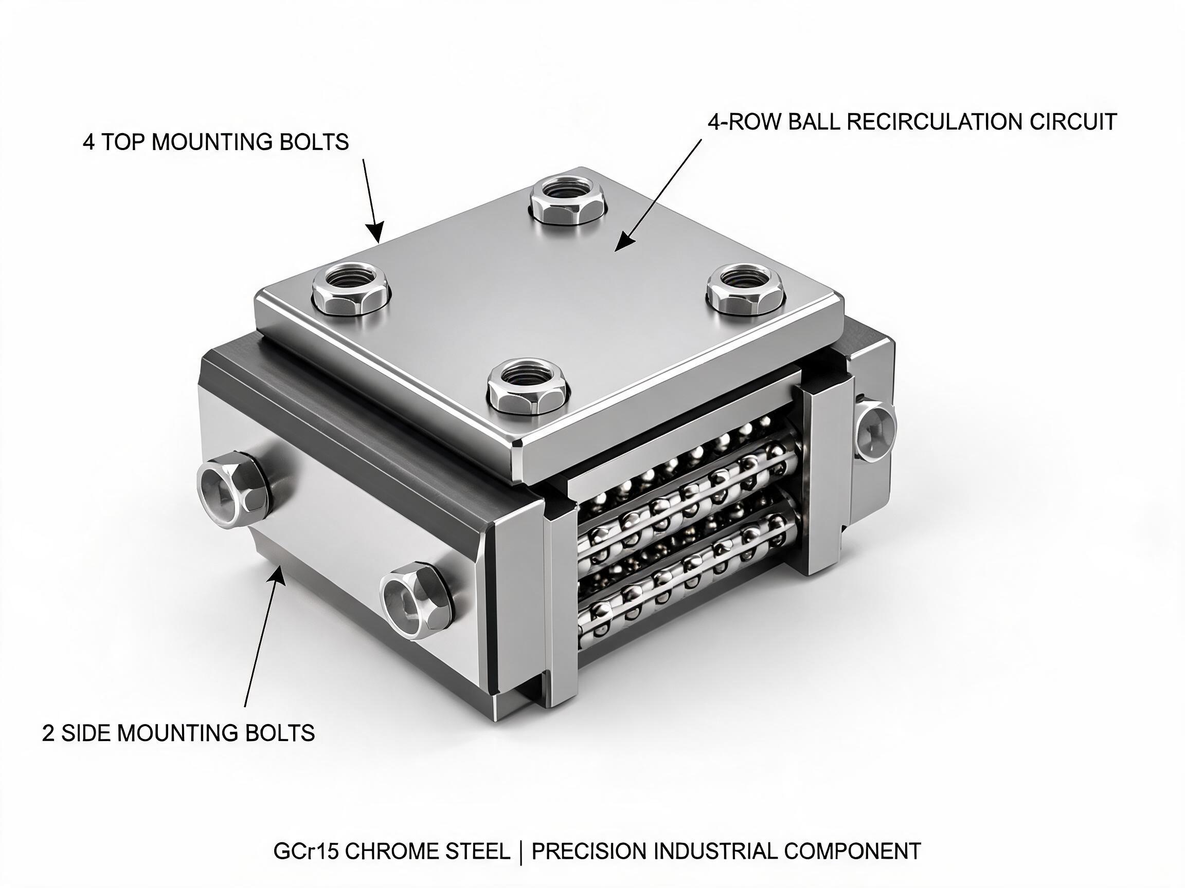
Moment loads are why a correctly rated linear guide can still fail when the carriage carries an overhung spindle head, cantilever gantry, or offset tooling. This guide explains pitch, roll, and yaw in plain terms, what each one does to ball contact and preload, why wider mounting footprints and longer carriage bodies resist moments, and when to move from a standard flange carriage to a wide-body carriage or to two carriages per rail.
A guide block that passes its dynamic and static load ratings can still fail on an overhung axis. The missing number in most selection sheets is not a force at all — it is a moment.
Key takeaways
- A linear guide rail moment load is created whenever the load centre is offset from the carriage centre — spindle heads, cantilever gantries, vertical axes and offset tooling all do this.
- An overhung part converts a modest force into a moment. Ball rows at the ends of the carriage take the highest contact stress even when the total load looks small.
- Wider mounting footprints and longer carriage bodies add lever arm. A wide-body carriage increases the bolt spread that resists pitch and yaw.
- Guide size is not the only lever: two carriages per rail or two rails per axis spread the moment across more ball rows.
- Ask the supplier for the load position, moment direction and preload grade — not just the dynamic rating.
Why an offset load is a moment
A load rating tells you how much force a carriage can carry when the force passes through, or close to, the carriage centre. Real axes rarely work that way. A spindle head hangs off the front of a Z axis. A gantry beam cantilevers past the rail. A gripper is mounted on a plate that puts the tool centre 150 mm away from the block.
Distance is what changes the problem. Force multiplied by the lever arm becomes a moment, and a moment is expressed in Nm or kNm — a unit that does not appear on a standard guide datasheet. That is the practical gap: the axis passes the force check and fails the moment check. The result looks like premature ball wear, a rough spot at the end of travel, a block that rocks under reversal, or a rail that shows contact marks at one corner of the raceway.
The same logic applies to a vertical axis. Gravity acts along the rail, which looks harmless, but any horizontal offset between the centre of mass and the carriage centre turns that weight into a moment about the rail. The larger the offset, the larger the moment for the same mass.
Pitch, roll and yaw on a rail axis
Engineers describe the three moment directions using aerospace names. On a linear axis, picture the rail as the reference line and the carriage as the body:
- Roll — rotation about the rail axis itself. The carriage tips sideways in the plane of the mounting face. This is the moment a tall, narrow structure creates, such as a vertical plate carrying a heavy tool.
- Pitch — rotation about an axis lying across the rail and horizontal. The carriage tips forwards or backwards along the direction of travel. A spindle sticking out in the travel direction produces pitch.
- Yaw — rotation about a vertical axis. The carriage twists so that its two ends try to move in opposite directions along the rail. A cantilever gantry whose mass sits to one side of the rail produces yaw.
In a real machine, the three rarely arrive separately. A tool offset in two directions, plus the centre of gravity above the carriage, produces a combination of roll, pitch and yaw at the same time. Each one pushes the internal load distribution of the carriage in a different direction.
What moments do to ball contact and preload
The carriage does not have one contact area. It has rows of balls running the length of the block, and moment loads make those rows work unevenly.
Consider a pure pitch moment. The front rows of balls compress and the rear rows unload, or the reverse depending on direction. The carriage stays inside its rated force envelope, yet the front rows now carry far more than their share. Do the same in roll, and one side of the block loads while the other relieves. In yaw, the two ends of the carriage fight each other along the rail.
A four-row ball circuit helps here because it can carry radial, reverse-radial and both lateral load directions. The HGR rail's four-row contact geometry distributes radial, reverse-radial and lateral loads across the raceways, and the carriage in the same family carries those same directions. That geometry is what lets a block resist moments in more than one sense — but it does not remove the uneven distribution caused by an offset load. It redistributes it.
Preload interacts directly with this. Preload removes clearance and makes the carriage stiffer, but a preloaded block with an uneven row load can run hot or notch. The self-aligning tolerance of the standard and wide-body carriage families is commonly ±0.5°, which absorbs minor mounting and rail parallelism error — it does not absorb a structural deflection caused by an overhung mass. If the machine frame bends, the guide sees the moment regardless of alignment tolerance.
Footprint, carriage length and bolt spread
The ability of a carriage to resist a moment depends on how far apart its load-carrying elements are. Two things buy that distance:
- Carriage length — a longer block places more ball rows further from the moment axis, which mainly helps pitch.
- Mounting footprint width — a wider bolt pattern puts the mounting bolts further apart, which mainly helps pitch and yaw, and stiffens the connection to the machine structure.
This is the engineering reason wide-body carriages exist. The HGW wide-body carriage has a mounting footprint roughly 20–30% wider than the standard HGH flange carriage, and its extended bolt pattern uses four top bolts plus two side bolts. That spread is what resists pitch and yaw moments — not a different ball size or a thicker block. The extra width is a lever arm.
The force ratings of the two families are close, so it is easy to assume they are interchangeable. They are not, once moments enter the picture:
| Item | HGH flange carriage | HGW wide-body carriage |
|---|---|---|
| Reference size | HGH20CA | HGW25CA |
| Dynamic load rating | 18.0 kN | 28.4 kN |
| Static load rating | 29.5 kN | 42.1 kN |
| Ball circuit | Four-row | Four-row, radial, reverse-radial and both lateral directions |
| Mounting footprint | Standard flange pattern | About 20–30% wider, extended bolt pattern (4 top + 2 side bolts) |
| Self-aligning tolerance | ±0.5° | ±0.5° |
| Preload grades | C0 / C1 / C2 | C0 / C1 / C2 |
Ratings shown are for the reference sizes named. Do not compare them as if they were the same size — a 25 frame and a 20 frame differ in rail width, bolt spacing and stiffness as well as in rating.
When to step up to a wide-body carriage
A standard flange carriage such as the HGH series flange-type linear guideway carriage block is the right default for compact axes where the load sits close to the carriage centre and the moment arms are short. Move to a wide-body carriage when any of these conditions applies:
- The tool or spindle centre is offset from the carriage centre by a significant distance in more than one direction.
- The structure above the carriage is tall enough that roll becomes the dominant moment.
- The axis reverses frequently under load, so the carriage rocks and the mounting joint works loose.
- Wear marks appear at one end or one corner of the raceway while the nominal load is well inside the rating.
- The mounting plate is thin and needs a wider bolt spread to reduce local deflection.
In these cases the HGW series wide-body linear guideway carriage block gives the axis a wider base and a longer bolt pattern to resist the same moment with less stress concentration. It is a geometry solution, not a capacity solution.
When two carriages or two rails are the better answer
Widening the block solves yaw and pitch only up to a point. If the moment arm keeps growing, the more effective change is to increase the number of contact zones, not the size of one.
- Two carriages per rail — spacing two blocks apart along the same rail increases pitch resistance, because the moment is now shared between two sets of ball rows separated by the mounting distance. The trade-off is a longer carriage assembly and a larger travel envelope loss.
- Two rails per axis — the classic choice for roll. Two rails with one carriage each create a base width that one rail cannot match, and the roll moment is split between the two guideways instead of being taken by one block.
- Rails on different planes — where the machine design allows it, mounting rails at an angle or on separate faces can place the reaction forces further from the moment axis.
Two rails with one carriage each also makes assembly less forgiving, because rail parallelism now matters twice. The HGR heavy-duty linear guideway rail family is the matching rail option when you need to carry radial, reverse-radial and lateral loads across the four-row geometry; see HGR series heavy-duty linear guideway rail for the rail side of the pairing.
What to confirm before ordering
Moment behaviour depends on the application, so the supplier cannot pick a carriage from a force rating alone. Prepare this information before you request a selection:
- Centre-of-gravity position relative to the carriage centre, in all three axes — including any tool or fixture mass.
- Direction and relative weight of the roll, pitch and yaw components, or enough geometry for the supplier to estimate them.
- Mounting hole pattern and plate thickness for the intended bolt spread.
- Rail spacing if more than one rail is used, and the distance between carriages if two are used per rail.
- Preload grade, and why it was chosen — C0, C1 and C2 behave differently under uneven row loads.
- Expected stiffness under load, and whether the machine frame or the guide is the softer element.
- Travel direction, acceleration profile and duty cycle, since reversing under moment load is the harshest condition.
- Whether the moment load has been calculated or only estimated. If it has not been calculated, say so.
Ask specifically how the selected carriage behaves when the load is offset, and whether the recommended block is chosen on force rating or on moment geometry. A supplier who can only quote the dynamic rating has answered half the question.
FAQ
Is a moment load the same as an equivalent load on the datasheet?
No. The dynamic and static ratings describe force capacity under defined conditions. A moment load is a separate effect created by the distance between the load and the carriage centre, and it changes how that force is distributed among the ball rows rather than simply adding to it.
Can a wide-body carriage replace a larger size of standard carriage?
Sometimes it is the better direction to go, because the wider footprint resists pitch and yaw without increasing the overall height of the frame. But the two are not interchangeable by rating: in the reference sizes above, the HGW25CA and HGH20CA differ in frame size, bolt pattern and rail width as well as in dynamic rating. Confirm the geometry of the actual axis before assuming a swap.
Does self-aligning tolerance absorb an overhung load?
No. A self-aligning tolerance of ±0.5°, as listed for both the standard flange and wide-body carriage families, accommodates minor mounting and rail parallelism error. It does not compensate for structural deflection caused by an overhung mass. If the frame bends, the guide sees the resulting moment.
How do I know the axis has a moment problem rather than a load problem?
Common signs are uneven wear at one end or one corner of a raceway, a rough or notchy feel when reversing direction at the end of travel, and loosening of the carriage mounting bolts — all while the calculated load is well inside the dynamic rating. Confirm with the actual load position and mounting geometry before changing the guide size.
Next step
If your axis carries an overhung spindle head, cantilever gantry or offset tool, send the centre-of-gravity position, the mounting footprint drawing and the preload grade you are considering. Comparing the standard flange and wide-body carriage options on the same axis geometry is a more useful conversation than comparing force ratings alone.