
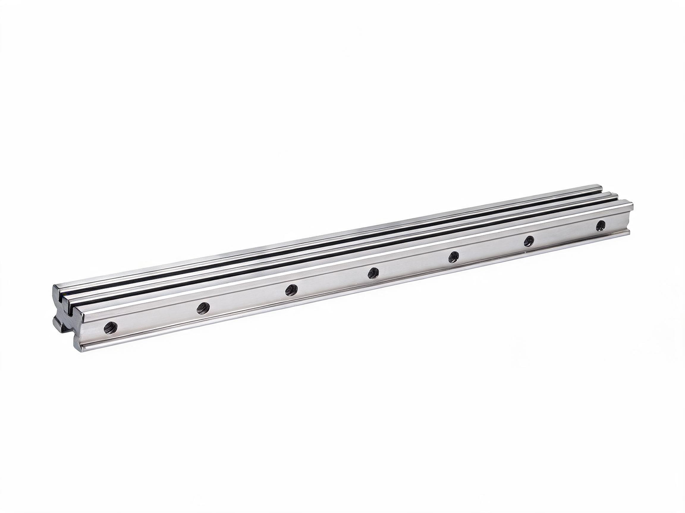
A practical, step-by-step mounting sequence for aligning two parallel linear guide rails on a machine base, covering datum edges, bolt-tightening order, running-parallelism checks, and the honest limits of carriage self-alignment.
Installation guide
Tightening the bolts that hold a linear guide rail is only half the job. The precision of the finished axis depends largely on how the two rails are set relative to each other. A rail that is straight along its own length but skewed across the span of the machine base will bind the carriages, load the bearing races unevenly, and shorten service life. The mount below is a practical sequence for a two-rail axis that machine builders can follow with standard hand tools and a dial indicator.
The method rests on one idea: the first rail fixes the datum. The second rail is then set relative to that datum, not relative to the base plate edge, the casting edge, or the operator's eye. Each of the four steps below assumes that the machine base has already been machined flat, cleaned, and checked; without that preparation, no mounting sequence will deliver parallel rails.
Step 1: Prepare the machined base and set the first rail
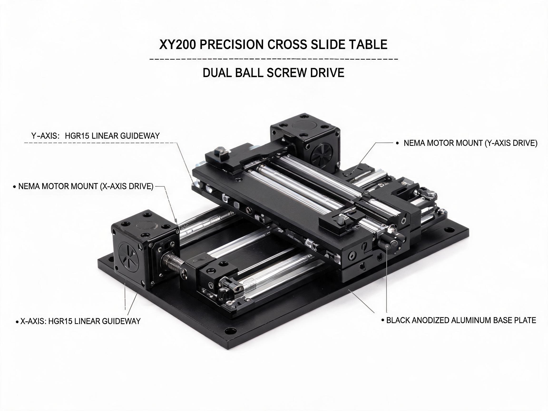
Before a rail is placed, the mounting surface must be a machined, flat reference surface. Burrs, paint ridges, chips, and dried coolant all sit between the rail and the base, and a rail pulled down onto an uneven surface will twist. Clean the surface, check for raised areas with a straight edge, and confirm that the bolt-hole spacing matches the rail.
Place the first rail against a datum edge machined into the base. This edge controls the lateral position of the rail along its full length. For the mounting bolts, follow the same practice used on MGN series rails: tighten progressively from the center outward to the manufacturer's recommended torque. Working outward from the center lets the rail settle evenly and avoids distorting it as the end bolts clamp down.
The rail grade sets the base accuracy the installation should support. Ground HGR rails in precision grade P5 are produced to a straightness of ≤0.02 mm/m on HGR45 sizes, which is a useful indicator of how flat and stable the mounting surface should be. Rolled N grade rails (P7) are a different product class and should be matched to the base accordingly. For the full dimensional and load range, see the HGR series heavy-duty linear guideway rail page.
For a rail that relies on a wide-body carriage, the HGW series wide-body linear guideway carriage block offers a self-aligning angular tolerance of ±0.5°, which compensates minor rail mounting errors without preload loss. That figure describes the carriage's tolerance, not the base's allowance; it is covered further in Step 4.
Step 2: Mount the second rail from a reference edge
The second rail should be positioned using the first rail as the reference, not a second feature on the base. A common practical method is to install the first carriage on the first rail, attach a temporary bridge or measuring bar to that carriage, and use a dial indicator held on the bar to sweep the second rail's reference edge. If the machine design provides a reference edge for the second rail, the indicator rides against that edge; if not, the rail side face itself becomes the reference.
Set the second rail so the indicator reading stays constant along its length. A constant reading means the two rails are parallel at the measured height; a reading that rises and falls indicates a skew that no carriage tolerance will remove. Do not assume the edge of the base plate is parallel to the first rail. The base edge is a convenient starting point at best, and on many weldments and castings it is not a controlled surface.
When two rail sections are joined end to end, align the butt-joint reference marks before final tightening. The joint is the place where a step or a lateral offset is easiest to introduce and hardest to see afterwards.
Step 3: Tighten in the correct order
Bolt order matters as much on the second rail as on the first. Tighten progressively from the center outward, in stages, up to the manufacturer's recommended torque. A staged sequence in which the center bolts are snugged first and the ends are brought down last lets the rail relax along its length instead of being locked into a curve. Check the indicator reading again after final torque; if the reading has moved, loosen, reset, and repeat.
The following table summarises the sequence and the reason for each step.
| Stage | Action | Why it matters |
|---|---|---|
| Surface | Clean and check the machined base; remove burrs and chips | Prevents twist and point loading |
| First rail | Set against the datum edge, tighten center-out | Establishes the reference for everything else |
| Second rail | Set from a reference edge using an indicator sweep | Controls parallelism across the axis span |
| Torque | Center-out in stages to the recommended torque | Avoids locking a curve into the rail |
| Check | Re-measure running parallelism | Confirms the axis before commissioning |
Step 4: Check running parallelism and respect the carriage's limits
Running parallelism is the final check. Mount a dial indicator on the carriage or on a fixture attached to the carriage, and sweep it along the reference face of the second rail over the travel of the axis. The standard grade MGN series figure is approximately 0.02 mm/300 mm, and the P grade is 0.01 mm/300 mm or better; the figure for other series and grades should be confirmed against the datasheet. Use the corresponding figure as the acceptance target for the axis, not a number borrowed from a different product line.
This is where the honest limit of self-alignment belongs. A self-aligning carriage with a ±0.5° angular tolerance can absorb a small amount of rail misalignment without losing preload. It cannot correct a base that is not flat, a rail that is bowed, or two rails that are visibly out of parallel. Trying to use the carriage tolerance as a substitute for base accuracy loads the bearing and produces uneven running, and the fault will return as wear or noise rather than as a clean alignment. Treat the tolerance as a margin for minor mounting variation, not as a correction device.
Common mistakes and what to check
- Trusting the base edge. The edge of a weldment or casting is rarely the reference the rail was designed to use. Measure from the first rail instead.
- Tightening end bolts first. This pins the rail ends and forces the middle into a bow, which the indicator will reveal only after final torque.
- Working on an uncleaned surface. A single chip under a rail can produce the same reading as a badly machined base.
- Skipping the post-torque check. A rail can move during tightening; the reading before torque is not the reading that matters.
- Expecting the carriage to fix the base. Self-alignment handles small angular error, not flatness or gross parallelism faults.
Frequently asked questions
Can I align two rails without a dial indicator?
A straight edge and feeler gauge can give a rough check, but they will not resolve the parallelism values that a precision rail grade expects. For a machine that will run at load, an indicator sweep is the practical minimum.
What do the HGR20 load figures mean for rail choice?
HGR20 rail is rated at 16.7 kN dynamic load and 26.7 kN static load. The load a carriage carries depends on the number of carriages, the mounting geometry, and the direction of the load, so confirm the arrangement against the datasheet before sizing.
Does rail material affect alignment?
HGR series rails are made from 55# high-carbon steel with raceways induction hardened to 58-62 HRC, and are available in sizes HGR15 through HGR45. Hardened, ground raceways hold their geometry under load, but they do not compensate for an inaccurate base.
When should I splice rail sections?
Only when the axis travel requires it. Align the butt-joint reference marks at the joint and check the running parallelism across the joint as well as at mid-travel, since the joint is a common location for a small step.
If you are specifying a two-rail axis and need rail and carriage data for the mounting surface you have, send the base drawing and the required grade. Our team can confirm the rail series, size, and carriage type against the datasheet.