
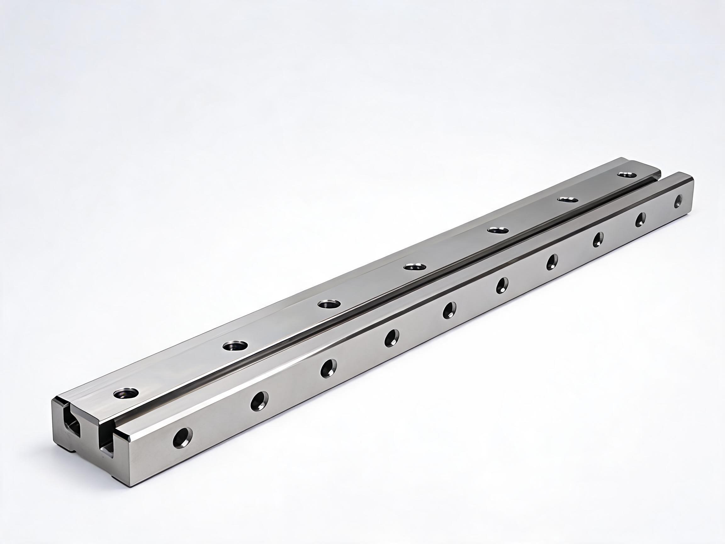
A practical explainer on dynamic load rating C and static load rating C0 for linear guide rails: what each value governs, how load direction interacts with a four-row ball circuit, and worked HGR20 and HGR45 examples that show which number to use for your application.
Linear Guide Rail Load Ratings: C, C0 and How to Use Them
A linear guide rail datasheet carries two load numbers, and buyers comparing profiles frequently ask which one governs their selection. They are not interchangeable. The dynamic load rating C is the reference value for a rolling bearing running under movement; the static load rating C0 is the limit against permanent deformation when the axis is at rest or takes a shock or overhang load. Applying the wrong number to your duty cycle leads either to an oversized rail or to a bearing that deforms before its expected life.
This article explains both ratings as general rolling-bearing principles, then works through two HGR examples so you can see which figure a given application should be checked against. For rated-life figures and the safety factor appropriate to your machine, confirm per datasheet or consult the supplier for your application.
Key points
- C (dynamic) is the rating for rated-life calculation under moving loads.
- C0 (static) limits permanent deformation at rest, under shock, or under overhang.
- A four-row ball circuit carries radial, counter-radial and lateral loads at the same time, so the load direction matters when you read the rating.
- The two ratings are not proportional to each other across sizes; compare the actual C and C0 of your chosen profile.
What the two load ratings mean
Both figures come from rolling-bearing practice. They describe the same bearing block under different operating conditions, so they answer different questions.
Dynamic load rating C
C is the load under which the rolling elements and raceways are rated for a defined fatigue life as the carriage moves. When the axis is running continuously and you need to estimate how long the carriage will last, or decide what safety margin to hold against a moving load, C is the number you start from. The life itself depends on the load magnitude, the load direction and the duty profile, so the life formula and its result are not fixed by C alone. Confirm per datasheet.
Static load rating C0
C0 is the limit against permanent deformation of the raceway when the bearing is stationary or when a load is applied without movement — a parked axis, a shock during handling, or a cantilevered carriage overhanging its support. A load above C0 does not wear the bearing out gradually; it leaves a permanent impression that changes running smoothness and accuracy for the rest of the axis life. That is why C0 is checked separately from C, and why it often governs machines that hold a heavy part at rest.
HGR20 and HGR45 load ratings
The HGR series values below show how the two ratings sit beside each other on real products.
| Profile / carriage | Dynamic load rating C | Static load rating C0 |
|---|---|---|
| HGR20 | 16.7 kN | 26.7 kN |
| HGR45 with HGW45CA carriage | 62.8 kN | 112 kN |
Values as listed for the named products. Rated-life figures and application safety factors: confirm per datasheet.
Note how the gap between C and C0 differs between the two rows: the C0/C ratio is about 1.6 for HGR20 and about 1.8 for HGR45 with the HGW45CA carriage. That ratio compares the two ratings only — it is not a safety factor or a life multiplier. Do not assume the same ratio carries across the whole size range — always read the two figures of the profile you intend to order.
Both sizes are available within the HGR Series Heavy-Duty Linear Guideway Rail, which covers sizes 15, 20, 25, 30, 35 and 45. The larger profiles are listed under the HGR45 Heavy-Duty Large Linear Guideway Rail.
Load direction and the four-row ball circuit
Ratings are stated for a load applied in a defined direction. In an HGR block the four-row ball circuit carries radial, counter-radial and lateral loads simultaneously. That matters because a machine rarely loads the carriage in a single clean direction: a gantry may put weight downward plus a moment from an offset tool; a vertical axis may press sideways as well as against the rail.
When you read C and C0 against your application, identify which directions actually carry load and how the resultant sits relative to the carriage. The published rating describes the bearing's capacity in its rated direction; if your machine loads the block in a combination outside that, the equivalent load calculation and the applicable safety factor need to be confirmed per datasheet rather than assumed. On a single-row or differently arranged carriage, the same direction question would be answered differently — do not transfer the HGR four-row layout across to other products.
Which rating governs your application
The decision is easier if you describe the duty cycle before you look at the table. Three typical patterns:
- Continuous moving duty. The carriage travels back and forth carrying a load. This is a dynamic case; C is the starting figure, and the life estimate depends on load, direction and duty profile.
- Static holding or parked load. The axis sits still with a weight on it — a fixture clamp, an inspection station, a stopped carriage under a heavy workpiece. Check C0.
- Shock or overhang. A sudden impact during loading, transport, or an offset cantilever that puts a moment on the block. Check C0, because a one-off overload leaves a permanent mark rather than wearing gradually.
Many machines fall into more than one category, and the correct approach is to check both: size the axis against C for the moving part of the duty cycle, then verify that the peak static load — shock, overhang, or parked weight — stays within C0 for the same block. Where the two checks disagree, the tighter one controls.
A worked comparison against an assumed requirement
Suppose a machine has a carriage carrying 8 kN radially in continuous travel, with a short parking phase where the same load is held at rest, and a shock during loading that peaks at an estimated 20 kN in the same direction. The figures below are hypothetical and are not a customer case; they simply show how the two published ratings are read against such a requirement.
| Check | Requirement (assumed) | HGR20 | HGR45 / HGW45CA |
|---|---|---|---|
| Moving load vs C | 8 kN radial, continuous travel | 16.7 kN — C is the figure to use for rated-life | 62.8 kN — C is the figure to use for rated-life |
| Static holding load vs C0 | 8 kN at rest | 26.7 kN — within the static limit | 112 kN — within the static limit |
| Shock peak vs C0 | 20 kN in the same direction | 26.7 kN — the peak is under the static limit | 112 kN — well within the static limit |
The table shows only that both sizes carry the assumed loads on the published ratings, not that they deliver the same life. Life is a function of load relative to C and of the duty profile, and the appropriate safety factor depends on the machine and its consequences of failure. Confirm per datasheet or consult the supplier for your application.
Now vary the requirement. A tool that overhangs the carriage far enough to put a heavy moment on the block, or an application where a poorly controlled load-up event can spike well above the working weight, is a C0 case first. A high-speed reciprocating axis with a light steady load is a C case first, because there the static peak never approaches C0. The rating you lead with should follow the condition that can actually damage or wear your block.
What a static load test can and cannot tell you
Static capacity is sometimes measured rather than only modelled. Supplier test records report HGR45 static performance as verified at 1.2× the rated static load on a hydraulic test rig; the test conditions behind that figure — the test object, load direction, holding time and acceptance criterion — are supplier-documented and should be confirmed with the supplier before being relied on for a specific machine. That result describes the block under that load in that test; it is not a general overload allowance, a warranty term, or a substitute for a safety factor in a real machine. If your design can see shock or overhang beyond C0, treat it as a design problem to fix, not as headroom to spend.
Material context for the rail itself
The rail is made from 55# steel, induction hardened to 58–62 HRC. Hardened raceways are what make the published load ratings meaningful for a rolling element running on the rail; if a rail is supplied in a different condition, the rating and the durability expectation need to be reconfirmed with the supplier for that supply. Match the specification of the rail you actually receive to the one the rating was stated for.
How to use the ratings in a purchase enquiry
State your case in the terms the ratings respond to. A useful enquiry names the profile and carriage, gives the moving load and continuous travel duty, gives the static holding load, and describes the shock or overhang condition with its direction and an estimate of magnitude. If your application needs a specific rated life, state the target and let the supplier confirm per datasheet. Where the load direction or the equivalent load is uncertain, ask for it to be confirmed against your mounting arrangement rather than assuming the rated direction.
A block selected on the number that never governs your duty will either be larger than necessary or will deform before you reach rated life. Matching the right figure to the right condition is the whole purpose of having both.
FAQ
Should I choose a linear guide rail by C or C0?
It depends on your duty. If the carriage moves continuously, C governs the rated-life calculation. If it is parked under load, or sees shock or overhang, C0 is the limit against permanent deformation and governs that condition. When both occur, check both and let the tighter one control.
Are the HGR20 and HGR45 static ratings proportionate to their dynamic ratings?
Not at the same ratio. HGR20 is listed at C = 16.7 kN and C0 = 26.7 kN; HGR45 with the HGW45CA carriage at C = 62.8 kN and C0 = 112 kN. Read the two figures of the profile you intend to order rather than scaling from another size.
Does the load direction change how I read the rating?
Yes. The four-row ball circuit in the HGR block carries radial, counter-radial and lateral loads at the same time, so identify which directions carry load in your machine and how they combine. If the combination sits outside the rated direction, the equivalent load and safety factor need to be confirmed per datasheet.