
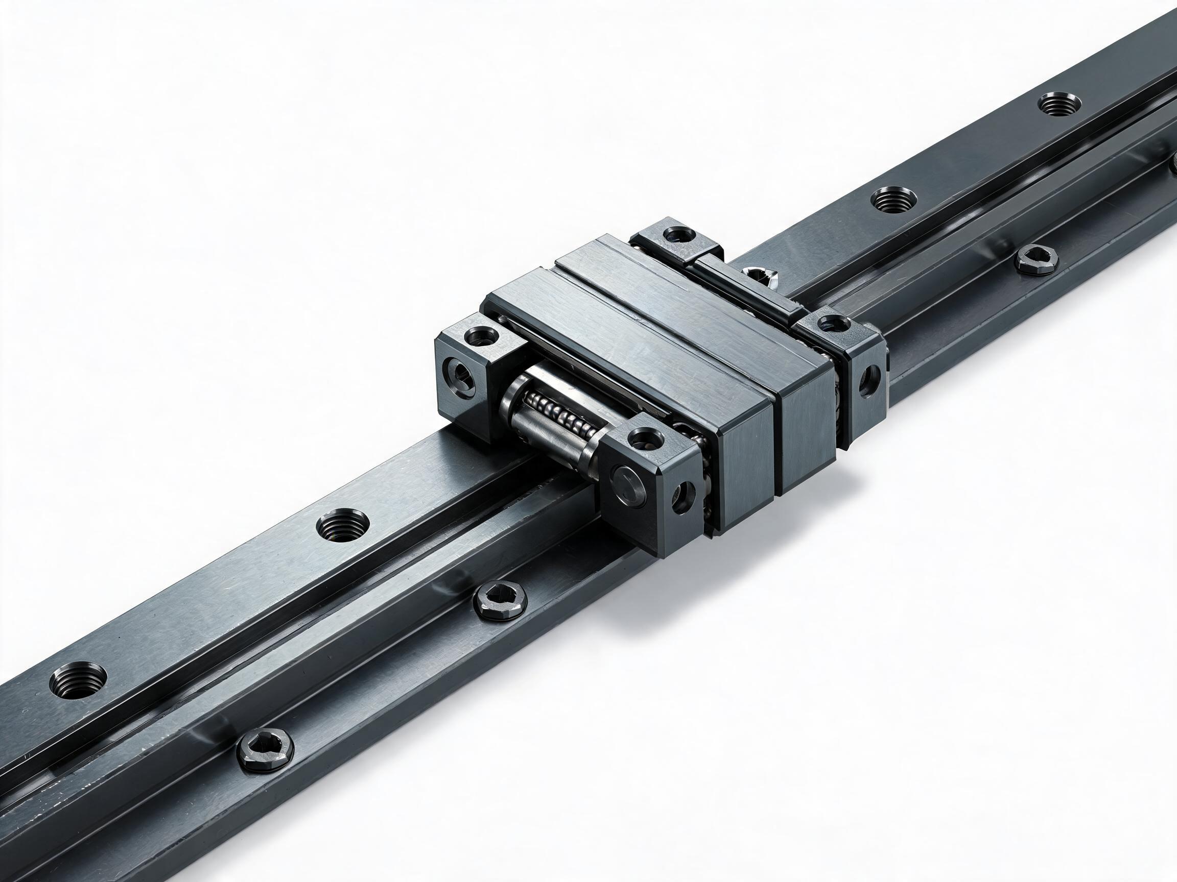
A practical guide for machine builders preparing a base for HGR-type profile rails: how hole pitch is tied to rail series and size, why bolt selection follows the rail, top-mounted through holes versus threaded base options, edge and end distances, and a pre-drilling checklist that avoids rework.
The linear guide rail mounting hole pattern is set by the rail series and size, not by the machine frame. Before you drill, the base has to be planned around that pattern: the pitch that repeats along the rail, the bolt the hole is sized for, whether you mount through the rail from above or thread into the base, and the distance you leave from edges and rail ends.
This article covers hole pattern, bolt choice and base preparation only. Two-rail alignment and shimming are a separate step and are not repeated here.
On this page
Key takeaways
- Hole pitch and bolt size vary by rail series and size; confirm them against the datasheet or drawing for your exact part.
- Plan base drilling from the rail drawing, then check the base can actually take that pattern.
- Through holes and threaded base holes are two mounting routes, not interchangeable without checking the rail type.
- Oversized holes give the installer room to move the rail, which also means less control over final position.
What the mounting hole pattern is standardized around
A profile rail such as an HGR Series Heavy-Duty Linear Guideway Rail carries a row of mounting holes at a repeating pitch along its length. That pattern is fixed by the rail family and its size, so the same series in different sizes will not share the same pitch or the same bolt requirement.
The hole spacing is not an arbitrary layout. It is sized so the number and position of fixings support the rail along its length and stay clear of the rolling contact zone. That is why the pitch, bolt size and hole diameter are taken from the rail drawing rather than chosen by the machine designer. The practical consequence: the base drawing must adopt the rail's pattern, or the frame must be modified to suit it.
For a larger rail in the same family, as with the HGR45 Heavy-Duty Large Linear Guideway Rail, the hole pattern scales with the section. This is why rail size has to be fixed before base fabrication, not after the rail arrives.
How the pattern maps onto the base
On a flat base, the rail holes translate into a row of positions along one axis. Three things must be readable from the drawing before any machining:
- The pitch that repeats along the rail (with any end offsets noted separately).
- The hole size and whether it is a plain hole or a counterbore.
- The bolt that fits the hole, and the head profile that bolt presents above or inside the rail.
Why matching bolt size to the rail matters
A mounting bolt does three jobs at once: it holds the rail down, it fits the hole without excess play, and its head has to clear the rail surface and any passing block. Mismatch on any one of these shows up as a mounting problem later. A bolt too small for the hole leaves the rail able to shift during tightening, which moves the reference edge you set during alignment. A bolt with the wrong head profile can protrude into a carriage's travel path or fail to seat in a counterbore. A bolt too large simply will not pass the hole.
The bolt also sets the required tapped depth or through-hole clearance: the base needs enough material beneath the hole to take the specified thread engagement, or enough open clearance for the bolt to pass and be tightened from the far side.
| Decision point | What to check before drilling |
|---|---|
| Rail series and size | Fixed and identified on the drawing; pitch and bolt size taken from that part's datasheet or drawing. |
| Mounting route | Through the rail from above, or threaded into the base, per the rail type and hole configuration. |
| Base material and thickness | Enough depth for full thread engagement, or clear passage for a through bolt. |
| Hole condition | Plain or counterbored, and whether any potting or sealing is needed for the mounting points. |
| Edge and end distances | Base supports the fixing without the hole breaking out at a frame edge or a rail end. |
A machined base versus a welded frame
The two base types fail in different ways, so the preparation differs.
Machined base
A machined plate or casting gives you a defined flat surface and predictable hole position. The main risk is that the hole pattern is drilled from the wrong reference or the hole is placed on the rail's nominal line rather than where the rail will actually sit. Drill from the same datum you will use to position the rail.
If the base is machined after the rail is on hand, check the pattern against the rail itself, not only against the catalogue figure.
Welded frame
A welded frame brings distortion and reduced tolerance at the fixing points. Welding heat can pull a plate out of flat, so holes drilled before welding may not line up cleanly afterwards. Where possible, weld and stress-relieve first, then machine the mounting surface and drill the hole pattern in a single setup.
On a welded frame, also check that the hole does not sit on a seam or in a thin unsupported region. A hole that lands partly on weld metal will not take the bolt cleanly.
Through holes and threaded base options
Rails can be mounted from the top through the rail's own holes, or from the base via threaded holes, depending on the rail type and hole configuration.
Mounting from the top
The bolt passes down through the rail hole into the base. The base needs either a tapped hole or a clear passage with access from below. This is the common route for a flat machined base with good access.
Threaded base
Threading into the base allows mounting where there is no access from above the rail. The thread position then has to match the rail hole pattern exactly, and the thread must be in material deep enough to hold it. A short thread in a thin plate is a weaker fixing than a full-engagement thread in a thicker section. Note that the presence of base threads in the drawing does not mean the rail you hold is designed for that route. That is a rail-type question, answered from the rail's own datasheet.
Counterbores and potting
A counterbore lets the bolt head sit within the rail's section rather than standing proud. The counterbore depth and diameter come from the rail drawing. Potting or sealing the mounting points is a separate choice; treat it as a question for the rail supplier rather than a default, and confirm what the rail's hole geometry allows.
Edge and end distances
Hole position is not just pitch and row position; it is also the distance from the nearest edge and from the rail ends.
- Frame edges. A hole too close to a machined edge can break out, leaving a partial hole that will not hold the bolt. Allow enough wall around the hole for the bolt load.
- Rail ends. The rail's first and last mounting holes sit at defined offsets from the ends. The base pattern has to carry those offsets, or a rail-end fixing lands where there is no support.
- Adjacent structures. Bolt heads and tightening access also need clearance, especially where a frame wall or another rail sits alongside.
Where the rail is longer than the base, consider whether the end holes still have support beneath them. An unsupported end fixing defeats the purpose of the hole.
Pre-drilling checklist
Work through this list before the first drill hole is marked.
- Rail series and size confirmed from the actual part, with the datasheet or drawing on hand.
- Pitch and bolt size read from that drawing, not carried over from a different rail size.
- Mounting route decided: through the rail from above, or threaded into the base, consistent with the rail type.
- Base drawing redrawn from the rail pattern, with the datum identified.
- Base thickness or section checked for thread depth or through-bolt clearance.
- Edge and end distances verified against the drawing, including the rail's first and last hole offsets.
- Welded frame stabilised and the mounting surface prepared before drilling.
- Counterbore or potting requirement resolved with the rail supplier for your part.
- Hole positions marked from the same datum used to position the rail.
FAQ
Is the mounting hole pitch the same for every HGR rail?
No. Pitch and bolt size vary by series and size. Confirm them against the datasheet or drawing for the specific rail you are using.
Can I drill the base from a generic catalogue table?
A catalogue entry is a starting point; the drawing for your exact part is the controlling document. If the two ever differ, treat the part drawing as authoritative and check with the supplier.
Should I use a larger hole to give myself adjustment room?
Oversized holes reduce accuracy. They allow the installer to move the rail, but they also remove the control that a correctly sized hole gives over final position. Where the design needs adjustment, that choice should be deliberate and made with the rail supplier.
Do I need to pot the mounting holes?
That depends on the rail's hole geometry and your machine environment. Ask the rail supplier before assuming either way, since a potting treatment changes what the hole is prepared for.
Why does a drilled base sometimes not line up after welding?
Welding can distort the plate, so hole positions drilled beforehand may move. Prepare and machine the mounting surface after stabilising the weld where the process allows it.