
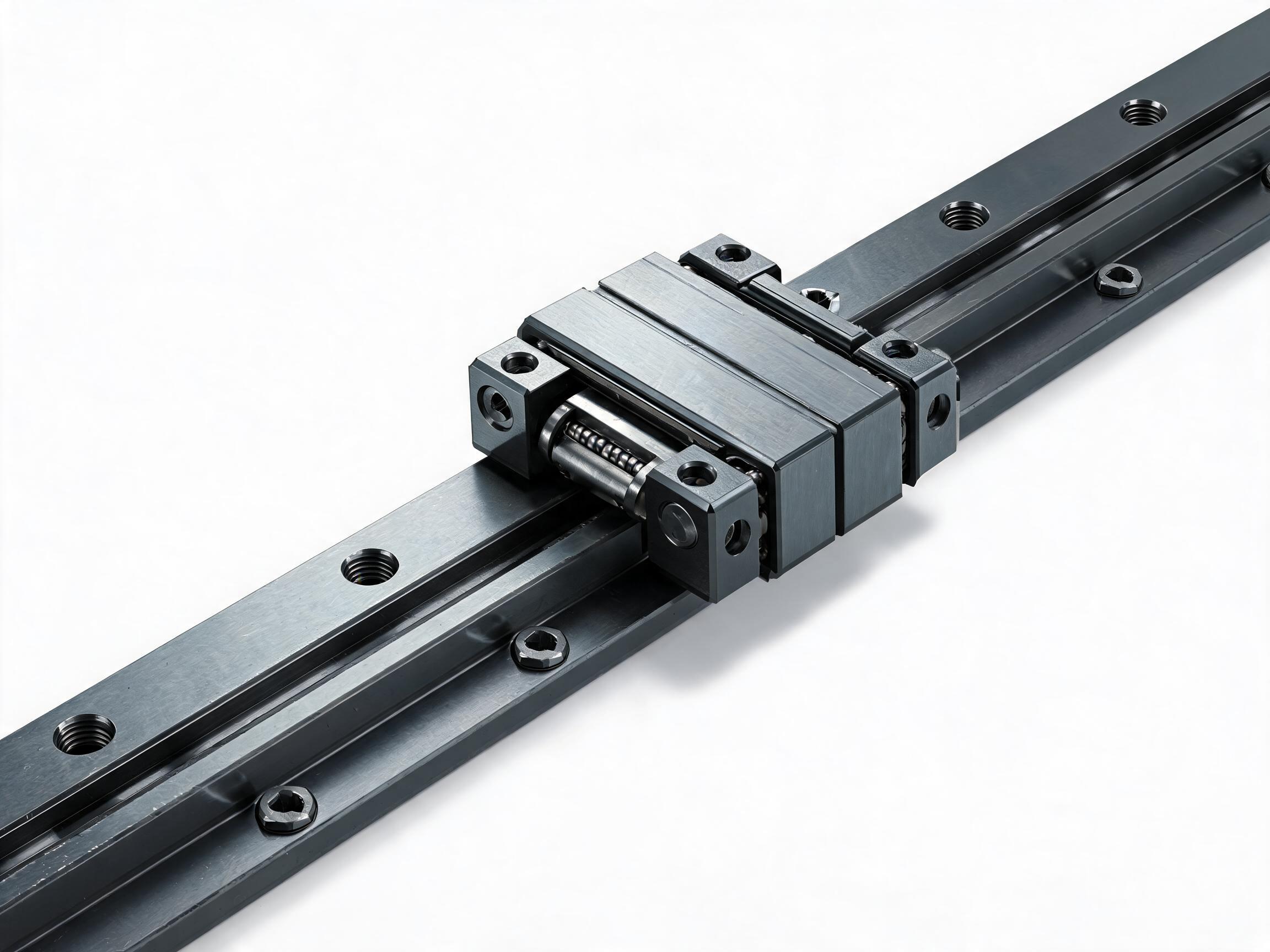
An axis-by-axis guide for buyers planning a linear motion system gantry or XYZ automation stage. It covers load and moment distribution on the bridge axis, the specific difficulties of Z-axis specification, when to use a self-built axis versus a pre-engineered rail module, and how to match the drive to the axis. It includes concrete specification examples from a 20 mm aluminum profile slide module and HGR-series heavy-duty rails, plus clear boundaries on what must be confirmed with the supplier for each layout.
A linear motion system gantry is specified one axis at a time, because each axis carries a different load, a different moment, and a different motion requirement. The X axis (the bridge) usually carries the most mass and the longest moment arm. The Y axis (the carriage on the bridge) carries the Z axis and its payload. The Z axis lifts the tool and is the axis where gravity, direction reversal, and counterbalance decisions come together. Treating all three axes as interchangeable rail-and-screw assemblies is where specification errors begin.
This guide walks through the decisions for each axis using concrete component data: a 20 mm aluminum profile slide module, HGR-series heavy-duty guide rails, and rolled ball screw drives. It also marks where the catalog facts stop and where a conversation with the supplier must begin for the specific gantry layout.
Key takeaways
- Size the bridge (X) axis by total moving mass and moment arm, not by payload alone.
- The Z axis is the hardest axis to specify because gravity acts along it and the load reverses direction on every stroke.
- Rails and carriages carry separate component ratings, and the lower of the two governs the axis.
- Match motor frame size and screw lead to the axis’s speed and load; a NEMA 17/23 mount footprint does not by itself confirm torque adequacy.
- Multi-axis stiffness, joint design, and Z counterbalance are not fixed by catalog data — confirm with the supplier for your layout.
On this page
The X (bridge) axis: load and moment
In a typical gantry, the X axis is the bridge beam spanning two side rails. It carries the Y carriage, the Z axis, the tool, and its own beam mass. When the Y carriage sits at one end of the bridge, that mass is cantilevered far from one side support — so the side rails see not only vertical load but a moment that increases with carriage position. That is why bridge rails are usually the largest rails in the system.
Specify the X axis in this order:
- Total moving mass. Sum the Y carriage, Z axis, tool, and beam mass. A 20 mm profile module at 500 mm stroke weighs 2.8 kg; the beam and Z stage masses are design-specific and need to be estimated separately for your layout.
- Moment arm. Measure from the side rail to the worst-case Y carriage position. The moment on the rail equals mass × gravity × that distance.
- Rail and carriage capacity. Rail and carriage carry separate ratings, and the lower of the two governs the axis. HGR20 rails are rated at 16.7 kN dynamic and 26.7 kN static; HGH20CA carriages are rated at 18.0 kN dynamic and 29.5 kN static, with preload C0/C1/C2 available on the carriage. HGR15 with HGH15CA is rated at 11.2 kN dynamic and 17.5 kN static. These are component ratings — compare them to the calculated load plus a margin you define, and remember that two carriages per rail share load only when the mounting is stiff enough to distribute it.
- Rail stiffness and flatness. HGR-series raceways are induction hardened to HRC 58-62, which supports the rail’s rated capacity. Mounting flatness affects how that capacity is realized.
If the calculated moment per carriage approaches the catalog rating, the next step is usually a larger rail size rather than more carriages on the same rail. The supplier can check the numbers for your bridge length.
The Y axis: carrying the Z stage
The Y axis moves along the bridge and supports the Z axis and tool. Its load is more constant than the X axis (the Z mass stays on it), but its moment arm changes as the tool’s center of gravity moves relative to the carriage. A short, rigid Y carriage block reduces that arm.
The Y axis is also where speed and accuracy usually matter most, because it positions the tool across the work area. A rolled ball screw such as the SFU1605 (5 mm lead, C7 accuracy, ±0.05 mm per 300 mm lead error, 6.8 kN dynamic load) gives a predictable trade between speed and resolution: a 5 mm lead means one motor revolution moves the axis 5 mm, so commanded resolution and achievable speed both follow from the motor’s speed range. The 20 mm profile slide module integrates this screw with a pre-drilled NEMA 17/23 motor mount and BK12/BF12 end supports, which shortens the mechanical build for the Y axis.
If the Y axis carries a large Z stage, check the module’s rail capacity and screw load against the combined mass before choosing between a 20 mm module and an HGR20-based self-built axis.
The Z axis: why it is the hardest
The Z axis differs from X and Y in three ways that drive its specification:
- Gravity acts along the motion. The drive must hold the tool up, not just move it. When the motor is unpowered or the brake is released, the load can fall unless a brake or counterbalance is provided.
- The load direction reverses. On the way up, friction and gravity resist; on the way down, gravity assists and the drive must control the descent. A rolled ball screw has low friction, which helps control but makes holding torque more critical.
- The stroke is short but the moment is not. A Z axis often has a short stroke, yet it mounts at the end of the Y carriage, so its mass contributes to the Y and X moment calculations. A heavier Z axis stiffens nothing — it loads every axis above it.
For a Z axis, specify: tool mass, required stroke, whether the tool pushes down or pulls up during work, whether the axis must hold position with power off, and the required repeatability. A self-built vertical axis using an HGR15 or HGR20 rail with a ball screw and a motor with a holding brake is a common approach. Counterbalance — a cylinder, counterweight, or spring — is a separate design decision; the catalog data for the modules and rails here does not include counterbalance sizing, so confirm with the supplier for your layout.
Module vs self-built axis
A pre-engineered module bundles rail, carriage, ball screw, end supports, and motor mount. A self-built axis lets you choose each component separately. The right choice depends on which work you want to own.
| Factor | Pre-engineered module (e.g., 20 mm profile slide) | Self-built axis (e.g., HGR20 + SFU screw) |
|---|---|---|
| Integration work | Rail, screw, BK12/BF12 end supports and NEMA 17/23 motor mount pre-installed | You align rail, screw, bearing supports and motor yourself |
| Load capacity | HGR15 rail with HGH15CA carriage: rated 11.2 kN dynamic, 17.5 kN static | HGR20 rail rated 16.7 kN dynamic, 26.7 kN static; HGH20CA carriage rated 18.0 kN dynamic, 29.5 kN static |
| Stroke flexibility | Standard 100/200/300/500 mm; custom to 1000 mm | Cut to any length within rail supply limits |
| Geometry | 20 mm profile width, 2020 T-slot compatible, 6063-T5 anodized aluminum | Depends on your frame design |
| Best for | Y axis, light Z axis, compact X axis | Heavy X bridge, long strokes, custom preload |
The 20 mm module’s 6063-T5 anodized aluminum profile and 2020 T-slot compatibility make it straightforward to bolt onto a T-slot frame. Its rail-to-base parallelism is stated at ≤0.02 mm, and each unit is full-stroke smoothness tested. Those are module-level specifications as listed; they describe the module, not a complete gantry’s accuracy. The load figures in the table are the internal rail and carriage component ratings; the module’s overall load and moment capacity, including the profile and end supports, must be confirmed with the supplier for your layout.
See the SKF20 aluminum profile linear slide module for full specifications, the SFU-series rolled ball screw assembly for screw options, and the HGR-series heavy-duty linear guideway rail for bridge-axis components.
Matching the drive to the axis
The motor mount footprint tells you which frame sizes fit; it does not tell you whether the motor’s torque is adequate. Match the drive in three steps:
- Lead and speed. With a 5 mm lead, axis speed = motor speed × 5 mm per revolution. A 5 mm lead favors resolution and thrust over top speed. If the Y axis must move fast across a wide bridge, check whether the required motor speed is within the motor’s continuous range.
- Thrust and torque. Required thrust = friction + acceleration force + gravity component (for Z). Required motor torque = thrust × lead / (2π × efficiency) + holding torque margin. The SFU1605’s 6.8 kN dynamic load rating is a screw capacity limit, not the thrust your motor will produce.
- Holding and braking. For Z axes and for X axes with a vertical component, confirm whether a holding brake is needed and whether the selected motor offers one.
Mounting a NEMA 17 or NEMA 23 motor to the pre-drilled module mount is a mechanical fit question; the torque calculation is a separate check. Ask the supplier to confirm the motor’s rated torque against the calculated requirement for your axis.
What must be confirmed with the supplier
The component data above supports rail selection, screw selection, and module integration. It does not answer everything a complete gantry requires. For each layout, confirm with the supplier:
- Multi-axis configuration. How the X, Y, and Z axes join, and what joint stiffness the design assumes.
- Z-axis counterbalance. Whether a counterweight, cylinder, or spring is required and how it is sized for your tool mass.
- Combined deflection. How the bridge beam, rails, and joints deflect under worst-case carriage position — the module and rail data are component-level, not system-level.
- Motor and drive matching. Motor torque, brake, and drive settings for each axis’s calculated load.
Company-level quality system certifications — ISO 9001:2015, CE, and an SGS factory audit — apply to the manufacturer’s management system, not to a specific gantry’s performance. Ask for the certificate scope relevant to your order.
Can I use a 20 mm profile module for the X bridge axis?
For a small gantry with a short bridge and a light Z stage, the module’s 11.2 kN dynamic rating (HGR15 rail with HGH15CA carriage) may be adequate. For longer bridges or heavier Z stages, calculate the moment per carriage and compare it to the component rating; if margin is thin, move to an HGR20-based self-built axis.
Does a 5 mm lead screw limit speed too much?
It depends on required traverse speed and motor speed. A 5 mm lead gives 5 mm of travel per motor revolution. If your required speed needs a higher motor speed than the motor’s continuous rating allows, consider a larger lead or a different drive. Confirm the speed requirement with the supplier.
Is the module’s ≤0.02 mm rail-to-base parallelism the gantry’s accuracy?
No. It is a module-level mounting specification. System accuracy depends on frame stiffness, joint design, screw accuracy (C7: ±0.05 mm per 300 mm), and the drive. Confirm the system accuracy target with the supplier for your layout.
Specify the X, Y, and Z axes separately, size the bridge by total mass and moment, treat the Z axis as a gravity-loaded axis with a holding requirement, and use module data for what it covers while confirming system-level behavior with the supplier.