
A practical guide for machine builders on stopping and holding a carriage on vertical or inclined profile-rail axes. It covers the three realistic strategies, why a standard carriage is not a holding device, and a selection checklist covering hold force, engagement type, duty cycle, and emergency-stop versus holding duty.
Linear Motion Selection Guide
When a carriage moves vertically or along an incline, gravity keeps pulling after the drive stops. A machine builder specifying a profile-rail axis therefore has to answer two separate questions: how the carriage is stopped under normal control, and how it is held when power is removed. A standard linear rail carriage does not do either job on its own.
This guide sets out the three realistic braking strategies for profile-rail axes, explains what a rail block can and cannot be asked to hold, and closes with a selection checklist covering hold force, engagement type, duty cycle, and the difference between emergency-stop and holding duty.

Key takeaways
- A standard rail carriage guides and carries load. It is not a holding device and will creep or back-drive under sustained gravity load.
- Ball screw self-locking is not a valid holding strategy for a vertical axis.
- The three realistic options are supplier brake or lock carriage variants, motor-side holding brakes, and external mechanical clamps or counterbalance systems.
- Brake holding force, response time, and safety ratings must come from the manufacturer datasheet, not from general assumptions.
Why a Standard Carriage Cannot Hold the Axis
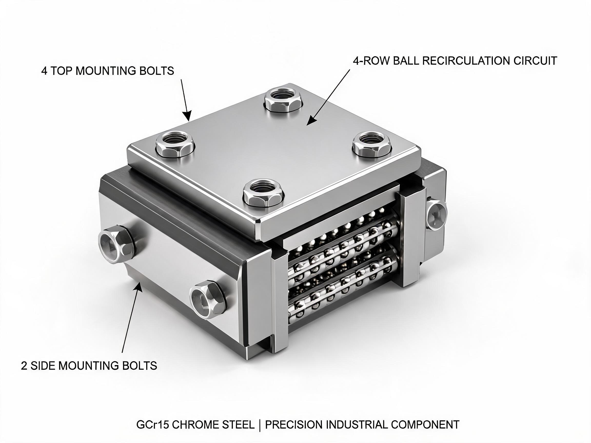
A linear guide carriage is designed to constrain motion in all directions except the travel direction, and to carry load through rolling elements. The ball circuit in a block such as the HGW Series wide-body carriage is built for smooth, low-friction translation. That low friction is the very property that makes it unsuitable as a brake.
For reference on capacity, the HGW25CA size in this series is rated at 28.4 kN dynamic load and 42.1 kN static load, available in sizes HGW15 to HGW45, with preload grades C0, C1 and C2 and a self-aligning tolerance of ±0.5°. These figures describe load-carrying capability, not holding capability. A carriage can support a heavy vertical load while still sliding down the rail once the drive is released.
The rail side does not change this. The HGR Series heavy-duty linear guideway rail is manufactured with a surface hardness of 58-62 HRC, and HGR20 is rated at 16.7 kN dynamic and 26.7 kN static. Hardened raceways improve wear life and load capacity; they do not add friction that would hold a vertical carriage in place.
Two consequences follow for machine builders:
- Any vertical or inclined axis needs a dedicated stopping and holding function, specified separately from the guide.
- Holding performance cannot be inferred from the dynamic or static load rating of the block.
Why Ball Screw Self-Locking Is Not a Holding Strategy
It is common to hear that a vertical axis is safe because the ball screw will not back-drive. Ball screws are low-friction rolling transmissions and generally do not self-lock in the way a lead screw with a steep friction angle might. Even where a particular screw and load combination shows very low back-driving tendency when new, that behaviour depends on preload, lubrication, wear, vibration and load direction, and it changes over the life of the axis.
Treat ball screw friction as a convenience at best, never as a safety function. If the carriage must stay in position with the drive de-energised, that requirement has to be met by a component designed for it.
Option 1: Brake or Lock Carriage Variants from the Supplier
Several guide manufacturers offer carriage variants that integrate a clamping or braking element into the block or an attached housing. These variants clamp onto the rail and hold the carriage in position. They are attractive because they keep the axis compact: no separate clamp bracket, no extra rail, and no change to the carriage mounting interface beyond the variant drawing.
The important limitation for buyers is availability and documentation. The site does not list a dedicated brake product, so brake or lock variants of the HGW and HGR ranges have to be confirmed with the supplier at the time of order, together with the exact variant code, drawings and datasheet.
When evaluating a supplier brake variant, ask for:
- Holding force or holding torque at the rail, and the conditions under which it is rated.
- Whether the element is spring-applied and power-released, or power-applied and spring-released.
- Response time from signal to full holding force.
- Permissible rail surface condition and any restriction on using a coated or jointed rail.
- Duty cycle and engagement frequency limits.
Do not substitute the block's dynamic load rating (for example 28.4 kN on HGW25CA) for a holding force figure. They are different quantities measured under different conditions.
Option 2: Motor-Side Holding Brakes
A holding brake mounted on the servo or stepper motor, or on the gearbox input, holds the drive train rather than the carriage directly. It is the most common route for vertical axes because it comes as part of the drive package and is well understood by control engineers.
Its effectiveness depends on everything between the brake and the carriage: the screw, the nut, the coupling, the carriage mounting and the rail. Backlash, compliance and any lost motion in that chain will show up as carriage movement when the brake engages. The brake also cannot protect against a failure downstream of itself, such as a nut wear condition or a coupling failure.
Motor-side brakes are a good fit for holding a stationary load during power-off and for parking between cycles. They are a weaker fit where the requirement is to arrest a moving load quickly, because the brake has to stop the reflected inertia through the whole drive train.
Option 3: External Mechanical Clamps and Counterbalance
Where the holding requirement is severe, frequent, or must be independent of the drive train, an external solution is the usual answer. Two families exist.
Rail-mounted clamps
A separate clamp unit grips the rail directly, usually with a spring-applied, pneumatically or electrically released mechanism. Because it acts on the rail, it is mechanically independent of the screw and coupling. The cost is space, an additional rail length for clamping, and a control signal for release. Rail hardness matters here: HGR rail at 58-62 HRC is a hard surface, and any clamp specification must state that it suits the rail it will grip.
Counterbalance
A pneumatic cylinder, gas spring or mass counterweight offsets part or all of the carriage weight. Counterbalance does not brake the axis by itself, but it reduces the load the brake has to hold and limits the consequences of a brake release. Many vertical axes combine counterbalance with a holding brake, using the counterbalance to reduce the required hold force and the brake to guarantee position.
Comparing the Three Strategies
| Strategy | Acts on | Best suited to | Main trade-off |
|---|---|---|---|
| Supplier brake/lock carriage variant | Rail, at the carriage | Compact axes needing position hold without extra hardware | Availability and specifications must be confirmed at order |
| Motor-side holding brake | Drive train | Power-off parking and holding a stationary load | Depends on screw, coupling and nut; does not protect downstream failures |
| External clamp or counterbalance | Rail directly, or the load | High hold force, frequent engagement, drive-independent safety | Extra space, cost and control signals |
Selection Checklist
Hold force needed
Calculate the force required to hold the carriage plus payload against gravity, then apply a margin appropriate to the risk of the axis. Include the mass of tooling, fixtures and any workpiece. If a counterbalance carries part of the load, the brake only needs to cover the remainder. Confirm the resulting figure against the datasheet value for the chosen brake, not against the guide rating.
Engagement type
Decide whether you need fail-safe engagement, where the brake applies on loss of power, or whether an energise-to-hold arrangement is acceptable. For vertical axes, fail-safe is normally the requirement. Confirm from the supplier which principle the offered variant uses.
Duty cycle
Count how often the brake engages per hour and per shift. A brake used to park the axis at the end of a cycle sees very different use from one that engages at every index position. Frequent engagement raises wear questions that only the manufacturer's duty-cycle data can answer.
Emergency-stop versus holding duty
These are different requirements and should not be met by the same assumption. Holding duty means keeping a stationary carriage in place against gravity. Emergency-stop duty means arresting a moving carriage, often with the full kinetic energy of the load and drive train. A component sized for holding is not automatically sized for stopping. Where an emergency-stop function is required, the stopping performance and any safety rating must be taken from the manufacturer datasheet and from the machine's own risk assessment.
What to Confirm Before Ordering
The specifications that decide whether an axis is safe are mostly not on the carriage datasheet. Before placing an order, confirm the following with the supplier:
- Whether a brake or lock variant exists for the specific carriage size and preload grade you have selected.
- The variant code and dimensional drawing, including any added length or mounting change.
- Holding force, engagement principle and response time from the datasheet.
- The rail condition the brake is designed to grip.
- Which safety or performance standards, if any, the brake is certified against.
Guide selection and brake selection run in parallel. The carriage capacity figures (for example 42.1 kN static on HGW25CA) tell you what the axis can carry; the brake datasheet tells you whether it can be held in place. Treat the two as separate decisions, and the vertical axis will behave predictably when power is removed.