
Support spacing for linear guide rails is not a single number — it depends on whether the rail is bolted to a machined base or spanning gaps on a welded frame. This article explains the two mounting worlds, what happens between supports when the span is too wide, the factors that tighten or relax spacing, and how one-piece and spliced HGR rails change the question entirely.
Mounting & Installation
How far apart linear guide rail supports can be is a question real buyers type into search engines — it comes from people bolting profile rails onto welded frames, extrusion structures, and machine beds that were never machined flat. The honest answer is that there is no universal distance, because the correct spacing depends on what the rail is sitting on. This article explains the two mounting situations, what a span that is too wide actually does to the rail and carriage, and what to settle before you order.
Key takeaways
- On a machined base with full-length contact, the base carries the load path — support spacing is not a variable at all.
- On a welded or extrusion frame with gaps, the rail itself must bridge each span, so spacing becomes a structural decision.
- Spacing that is too wide shows up as local deflection under the carriage: uneven preload, rougher travel, and faster raceway wear.
- Rail size, where the carriage sits at peak load, duty type, and actual base flatness all move the answer in either direction.
- One-piece HGR rails up to 4,000 mm avoid the question; longer runs use joined sections with precision splice joints held to the same straightness grade across the splice.
What this article covers
Two mounting worlds
Almost every support-spacing question traces back to which of two situations the machine builder is in, and the two have completely different answers.
Machined base, full-length backing
The rail is bolted down continuously along its full length onto a machined or ground mounting face. The face carries the load path, and the rail simply follows it. In this arrangement there is no meaningful "support spacing" decision: the spacing of the mounting bolts is set by the rail's own bolt-hole pattern, not by a decision about how far the rail can be allowed to span unsupported.
Two conditions make this work. First, the base has to be flat to the tolerance the rail grade expects — a ground H (P5) rail sitting on a face that has been machined is the standard case. Second, you need a full-length backing surface, not a series of pads. It is the continuous contact that transfers load out of the rail and into the structure.
Welded or extrusion frame, spanning gaps
The rail is mounted across a frame that is not continuously machined — a welded steel structure with intermittent cross members, or an aluminium extrusion frame with rails bolted at intervals. Here the rail is not supported everywhere; between mounting points it spans open gaps, and the rail section itself has to carry the carriage load across each span. This is the situation in which support spacing becomes a real engineering variable that has to be considered, because the rail is now acting as a beam between its attachment points.
What happens between supports when spacing is too wide
Nothing dramatic happens the first time. The rail is steel, and it will not visibly sag. The problems start at the surface where the carriage balls run.
- Local deflection under the carriage. The load of the carriage pushes the rail down into the gap between two mounting points. The rail bends very slightly, but the bending happens exactly where the rolling elements contact the raceway — the worst possible location.
- Uneven preload along the length. A preloaded carriage is set up to run with a defined contact condition. If the rail deforms between supports, that condition changes as the carriage travels: tighter over a mount, looser over a gap.
- Rough or inconsistent travel. The carriage feels different depending on where it is on the rail. Operators report stick-slip, vibration, or a notch at the mounts.
- Accelerated raceway wear. The raceways of an HGR rail are induction hardened 58–62 HRC, which is hard, but hardness does not protect against a contact load that keeps shifting as the rail flexes. Wear concentrates where deflection and loading are highest.
The practical symptom is a machine that passes inspection when the carriage is parked over a mount and behaves differently when it is over the gap. That is usually the first sign the spans are too wide for the load.
Factors that tighten or relax spacing
There is no single recommended spacing figure that applies across machines, because several interacting factors set it. What matters is understanding which way each one pushes.
| Factor | Pushes spacing tighter | Allows wider spacing |
|---|---|---|
| Rail size (HGR 15–45) | Smaller sections deflect more under the same load | Larger sections carry more over the same span |
| Carriage position at peak load | Peak load lands mid-span, or the carriage overhangs the end | Peak load always sits near a mounting point |
| Duty type | Continuous dynamic cycling with varying load | Static or lightly loaded positioning |
| Base flatness | Frame face is wavy, so mounts do not all seat the same | Frame face is straight and consistent across its length |
| Preload class | Preloaded carriages are more sensitive to rail bending | Non-preloaded carriages tolerate more variation |
Two of these deserve more attention than they usually get.
Carriage position at peak load. Support spacing is often discussed as if the carriage were a distributed load sitting in the middle of the machine. It is not. Ask where the carriage is when the load is highest — the moment of heaviest cut, the maximum overhung tool, the clamping point. If that position is over a gap, that gap is the one that governs.
Base flatness. A welded frame is never as flat as a machined face. The rail will follow the shape of the frame, which means the carriage encounters the same waves. If the frame face varies over its length, tightening support spacing adds mounting points but does not necessarily make the surface the carriage runs on any straighter — it only reduces the span the rail has to carry on its own. Both the span and the underlying straightness matter.
One-piece rails and precision splice joints
There is a way to make support spacing a non-question, and it is worth considering before designing around gaps at all.
The HGR series is supplied in sizes 15, 20, 25, 30, 35, and 45, with standard lengths up to 4,000 mm per rail. Within that range, a single continuous rail means the carriage never crosses a joint and never has to span an unsupported break. If your travel fits within a standard length, one piece is the simplest answer to the whole problem.
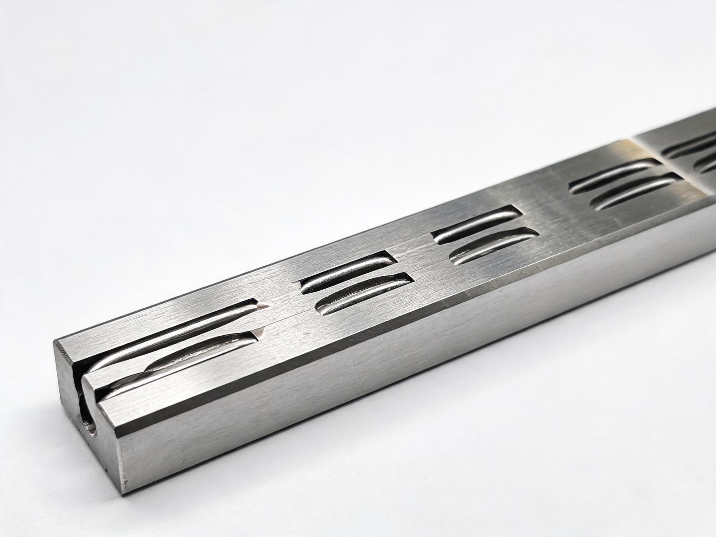
For longer runs, rails are produced as joined sections with precision splice joints. The relevant point for machine builders is that straightness is held to the same grade across the splice as it is along the rest of the rail. That is what makes a joined rail usable for a carriage that has to pass over the joint — the rolling elements encounter a continuous raceway geometry rather than a step. To be clear about what this does and does not mean: a splice joint solves the problem of rail continuity, but it does not add stiffness to a span. If the rail between mounting points must carry a bending load on a welded frame, that is still a structural question for the frame design.
A pre-order checklist
Before specifying an HGR rail for a machine, settle these five items. Each one changes either the rail selection or the frame design, and getting them wrong is expensive after the rail has been cut.
- Base type. Is the rail going onto a machined mounting face, or onto a welded steel or aluminium extrusion frame? This single answer determines whether support spacing is a fixed bolt pattern or a structural calculation.
- Base flatness. How flat is the mounting face over its full length, measured — not assumed? This limits which rail grade makes sense and how much the rail will have to compensate.
- Span. If gaps exist, what is the longest unsupported distance, and where does it fall relative to the carriage at peak load?
- Rail size. HGR 15 through 45 cover a wide stiffness range. The section size has to be chosen against the span and the load, not chosen first and justified after.
- Whether spliced rail is acceptable. If the travel exceeds a standard 4,000 mm rail, confirm that a precision splice joint is acceptable for the application and that the carriage has to cross it.
FAQ
Is there a standard recommended support spacing for linear guide rails?
No single figure applies across machines. On a machined base with full-length backing, the rail is continuously supported and spacing is just the bolt-hole pattern. On a frame with gaps, the allowable span depends on the rail size, the load, where the carriage sits at peak load, and the duty. It has to be worked out for the specific machine rather than taken from a table.
Can a linear guide rail span an unsupported gap?
Yes — that is exactly what happens on welded and extrusion frames. The rail section acts as a beam between its mounting points and carries the carriage load across the gap. The question is not whether it can span a gap, but whether the deflection across that particular span is acceptable for the carriage and the process.
Does a longer rail need more supports?
A single continuous HGR rail up to 4,000 mm does not need intermediate supports in the sense the question implies — it is bolted along its full length to whatever face it is mounted on. Where the frame provides only intermittent contact, the number and position of contact points is a frame design decision. The rail length itself does not change the physics of how the rail is backed.
How straight is a spliced rail across the joint?
HGR rails longer than the standard 4,000 mm are supplied as joined sections with precision splice joints, and straightness is held to the same grade across the splice as along the rest of the rail. The rail is made from 55# high-carbon steel, induction hardened to 58–62 HRC, and is available in ground H (P5) and rolled N (P7) grades.
Where this leads
The support-spacing question usually resolves into one of two decisions: either the machine has a machined base and the rail simply follows it, or the machine has a welded or extrusion frame and the span has to be designed. In the first case, the rail is the only variable. In the second, the frame and the rail have to be considered together.
For applications that fit within a standard length, the HGR series heavy-duty linear guideway rail covers sizes 15 through 45, in standard lengths up to 4,000 mm, in ground H (P5) and rolled N (P7) grades, with longer runs supplied as joined sections. If your travel exceeds that, confirm the splice requirement and the frame's support conditions before the rail is cut — those two items determine whether a standard rail works or whether the frame needs another support under the carriage path.
Support spacing is a frame-and-load question rather than a rail catalogue figure. Bring the base type, the measured flatness, the longest span, and the carriage position at peak load, and the rail selection follows from there.