
A manual linear stage is a positioning table moved by hand knob or micrometer, not a motorized slide. This article explains what manual stages are, the specific situations where they outperform motorized alternatives, their inherent limits, and the exact specifications buyers should confirm before ordering. It also clarifies the boundary with motorized-stage selection, which is covered separately.
If you are specifying a positioning axis and the adjustment happens once per setup, a hand-driven table can be the more practical purchase. A manual linear stage is a linear bearing platform moved by a knob or micrometer spindle. The operator turns the dial, the table travels, and a lock holds the position. No controller, no drive tuning, no homing sequence. This article covers what these stages are, where they genuinely beat a motorized slide, their limits, and the specifications a buyer should confirm before quoting. Motorized-stage selection is a separate question; this page stays on the manual side of that boundary.
Key takeaways
- A manual linear stage is a bearing-guided table driven by a hand knob or micrometer, with position read from the dial and held by a lock.
- It wins where the axis is set once per run: lab fixtures, optical alignment, inspection setups and low-duty positioning.
- It loses where the process needs programmed moves, closed-loop position, or repeated high-duty cycling.
- Repeatability is a function of the operator and the mechanism, not a controller; treat the datasheet value as a statement of conditions.
- Specify four things before RFQ: travel, per-division resolution, lock behavior, and load and moment capability.
What a manual linear stage actually is
A manual linear stage, sometimes called a hand-adjusted positioning table or a micrometer-driven stage, consists of a base, a linear guide (often a crossed-roller or ball-bearing way), a moving carriage, and a drive screw turned by a graduated knob or micrometer head. On single-axis units the carriage moves in one direction. A manual xy linear stage stacks two such axes, usually with the lower axis carrying the upper one, giving independent X and Y adjustment in one assembly.
The position is read from the dial graduation and set by hand. A clamp or locking screw fixes the carriage after adjustment so the setting survives touch, load changes or vibration during the run. There is no encoder and no motor; the readout is mechanical.
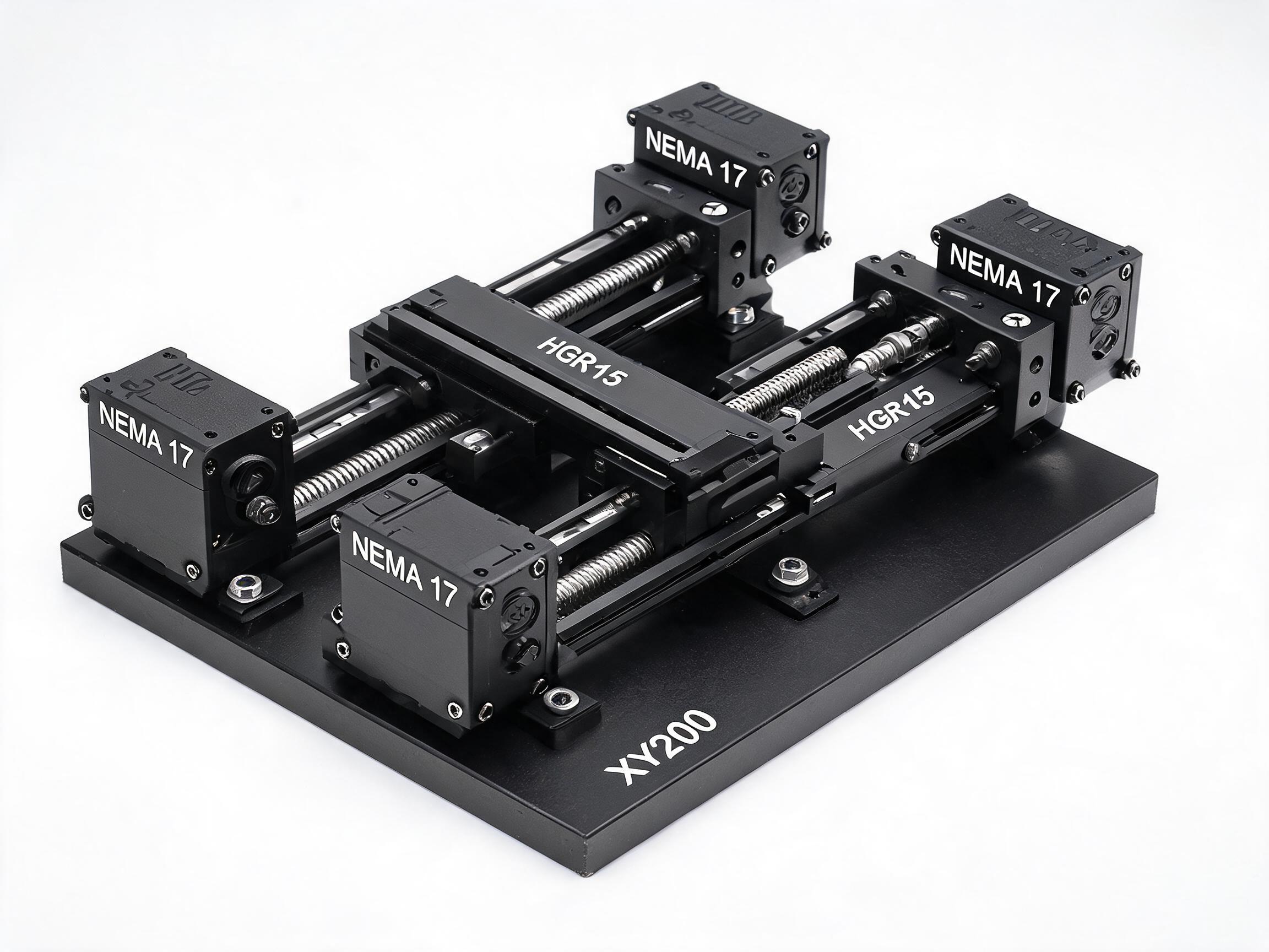
This is a different category from the motorized precision stages we build and list, such as the XY200 precision cross slide table. That unit uses dual HGR15 guideways and SFU1605 C7 ball screws per axis, delivers 200 mm travel per axis, is CMM-verified to 90° ± 0.02° orthogonality, lists ±0.01 mm repeatability, and accepts a NEMA 17 interface for motor drive. It is the motorized counterpart a buyer graduates to when the manual axis outlives its job. Our standard catalog tables are motor-driven; manual dial stages are quoted on request.
Where a hand-adjusted stage is the better buy
The decision is not about precision. It is about how often the axis changes position and who changes it.
Set-once adjustment
When an axis is dialed to a position at the start of a run and left there, the cost of a motor, drive, controller and cabinet is spent on functionality the process never uses. A manual stage needs a power drop and a hand. The setup sheet records the dial value; the next operator repeats it.
Lab fixtures and inspection benches
Probe positioning, sample alignment under a microscope, and fixture setup are typically low-cycle, high-variety tasks. A manual XY stage lets an engineer nudge alignment by hand while watching the result, which is often faster than jogging a motor through a teach pendant for a one-off alignment.
Optical alignment
Centering a lens, a fiber, or a sensor in a beam path usually requires small, deliberate moves with immediate visual feedback. A micrometer head gives the operator a direct dial-to-motion relationship at the point of adjustment.
Low-duty positioning
If the axis moves a few times per shift, the duty cycle does not justify drive electronics. Manual stages also suit environments where adding powered actuators and cabling is undesirable, subject to the facility's own rules.
| Selection factor | Manual stage | Motorized stage |
|---|---|---|
| Position change frequency | Once per setup or occasional | Frequent or programmed |
| Control architecture | Operator hand, dial readout | Drive, controller, feedback |
| Motion profile | Direct manual move | Programmed or jogged |
| Repeatability source | Mechanism plus operator technique | Mechanism plus closed-loop control |
| Integration effort | Mount and align | Mount, wire, tune, home |
| Best fit | Fixtures, alignment, low duty | Automation, scanning, high duty |
Qualitative comparison; no performance numbers are implied beyond the categories.
The limits you are accepting
- No automation. A manual stage cannot run a scan, index on a schedule, or execute a program. If the axis must move as part of an automated sequence, the manual option is the wrong boundary.
- Repeatability depends on the operator. Returning to a dial mark by hand is a practiced skill. Two operators, or the same operator on a different day, can land differently. The mechanism's repeatability figure in a datasheet describes conditions, not a guarantee for every user.
- Human error is unmonitored. There is no encoder to catch a misread dial or a forgotten lock. Process documentation has to carry that burden.
- Duty and wear. Hand adjustment repeated at high cycle count is slow and wears the operator and the mechanism. That is a use case for motor drive, not for more manual effort.
- Locking matters more. Without a reliable clamp, drift under load or vibration can undo the setting.
How to specify a manual linear stage
Send the supplier a requirement statement, not a wish list. Four parameters drive the quote.
1. Travel
State the usable stroke needed per axis, in millimeters, and whether the requirement is for an XY arrangement or a single axis. Travel drives the bearing length and the screw, so it is the first number in the RFQ. If the application has a known working envelope, give it; do not leave the supplier to guess from a drawing photo.
2. Per-division resolution
This is the smallest position step the dial graduation represents, and it depends on the screw lead and the graduation count. It is not the same as repeatability. Ask the supplier to state the per-division increment and the repeatability separately, with the conditions for each. This article does not quote a number because it must come from the confirmed datasheet for the specific model quoted.
3. Lock behavior
Confirm the locking method, where the clamp acts, and whether the axis can be locked without disturbing the setting. For an XY stack, ask whether each axis locks independently.
4. Load and moment capability
Give the static load, the overhung load, and any moment the fixture applies. A cantilevered load on a small stage deflects; the supplier needs the actual mass and lever arm to size the guide. Also state mounting constraints: bolt pattern, available footprint, and orientation.
Also worth stating in the RFQ
- Operating environment: benchtop, vacuum, cleanroom, or temperature range.
- Readout requirements: direct dial reading versus digital indicator (if offered).
- Material and finish preferences, if the facility has them.
- Any calibration or inspection documentation the buyer expects, and who performs it.
Do not assume every manual stage comes with a calibration certificate; ask. Likewise, confirm the mounting interface matches your fixture before ordering.
When the manual stage has done its job, the axis moves to motor drive
A common trajectory: a lab setup starts with a manual XY stage for alignment, then the process matures into an automated scan or a production sequence. At that point the requirement changes from set-once to programmed motion, and the motorized stage question comes back into scope. Our XY200 cross slide table is the kind of unit that answers it: dual HGR15 guideways and SFU1605 C7 ball screws, 200 mm travel per axis, 90° ± 0.02° orthogonality verified on a CMM, ±0.01 mm repeatability as listed, and a NEMA 17 motor interface. For that transition, the selection logic is set out in our separate motorized-slide article; this page deliberately does not repeat it.
FAQ
Can I buy a manual stage from your catalog?
Our standard listed tables are motor-driven. Manual dial stages are quoted on request, so send the travel, resolution, lock and load requirement to the sales contact and the quote will be prepared against those parameters.
Is a manual stage as precise as a motorized one?
Precision and repeatability are different properties. A manual stage's return accuracy comes from the screw, guide and operator technique; a motorized stage adds closed-loop control. Compare them on the specific numbers each supplier lists, under stated conditions, not on the mechanism type alone.
What is the difference between a manual linear stage and a manual XY linear stage?
An XY unit stacks two single-axis stages at right angles, usually with the lower axis carrying the upper. An XY assembly needs attention to orthogonality between the axes and to how the upper axis locks without moving the lower one.
Can the dial be replaced or fitted with a digital readout?
Readout arrangement depends on the specific model. Ask the supplier which readout options the quoted stage supports and whether the graduation or indicator can be changed without altering the drive.
What should I include in a manual stage RFQ to get a usable quote?
Travel per axis, per-division resolution, lock requirement, static and overhung load, moment, mounting pattern, environment, and any inspection documentation expected. That set lets the supplier quote a specific configuration instead of a family description.