
After a linear axis is bolted down, rough travel usually points to the frame or the mounting sequence, not the unit. This article covers the datum surface, parallelism, tightening order, over-constraint when a second rail or axis is added, and how to verify free travel over the full stroke on real slide units, guide rails, and motorised modules from Xiamen Dongfeng Bearing Mechanical & Electrical Co., Ltd.
Assembly & Alignment
You have the unit on the bench and the frame in front of you. The carriage does not glide. It binds near one end, feels heavy in the middle, or needs a push to get moving. In most cases the unit is fine; the frame is not, or the mounting sequence introduced a twist that the carriage cannot absorb. The causes are specific and repeatable, and they show up again when you add a second rail or a second axis to the same structure.
The checks below are the same ones we use when we help buyers commission the SBS16, SKF20 and HGR series. Some you can do on site; one needs a supplier measurement. Every check anchors to a real mounting feature on the parts.
The checks that decide whether travel stays free
- A flat, clean datum face before the rail or profile goes on, with no burrs or leftover paint at the fixing holes.
- One datum edge that locates both the rail and the carriage travel, not two edges that fight each other.
- A tightening order that walks from the centre outward and repeats at partial torque (where a torque cycle is specified).
- When a second rail or second axis is added, no second datum that pulls the first into an S-bend.
- A full-stroke, both-end check by hand and by loaded move — light at both ends, no change in effort along the length.
On this page
What the frame must be before the unit goes on
A linear unit assumes the face it sits on is flat. It is not a flexible coupling. If the frame face is bowed or twisted, the rail or profile base will follow it, and the carriage or module will tighten where the geometry pushes the rail out of line.
Before the unit goes on:
- Clean the mounting face and the fixing holes. Chips, weld spatter, and overspray at the hole edge act as a local spacer.
- Check the face with a straight edge and a feeler gauge along the full length of the axis, not just at the ends.
- Check the frame is not twisted. Two diagonal references on the same face should agree; if they do not, the face is not planar.
- Deburr the mating face of the rail or the profile base, and any machined pocket that receives it.
- Confirm the frame material can hold the fixing load without local yielding. A tapped hole in thin sheet will deform before the bolts reach their seat, and the rail will spring back once it is loaded.
A common mistake is to bolt a unit onto a welded frame and use the fixing bolts to pull the rail down. The bolts will do this, but the rail then holds a permanent bend. The carriage feels rough even though the rail is dimensionally correct. If the frame is not flat, machine or shim the frame; do not force the rail.
One datum edge, used consistently
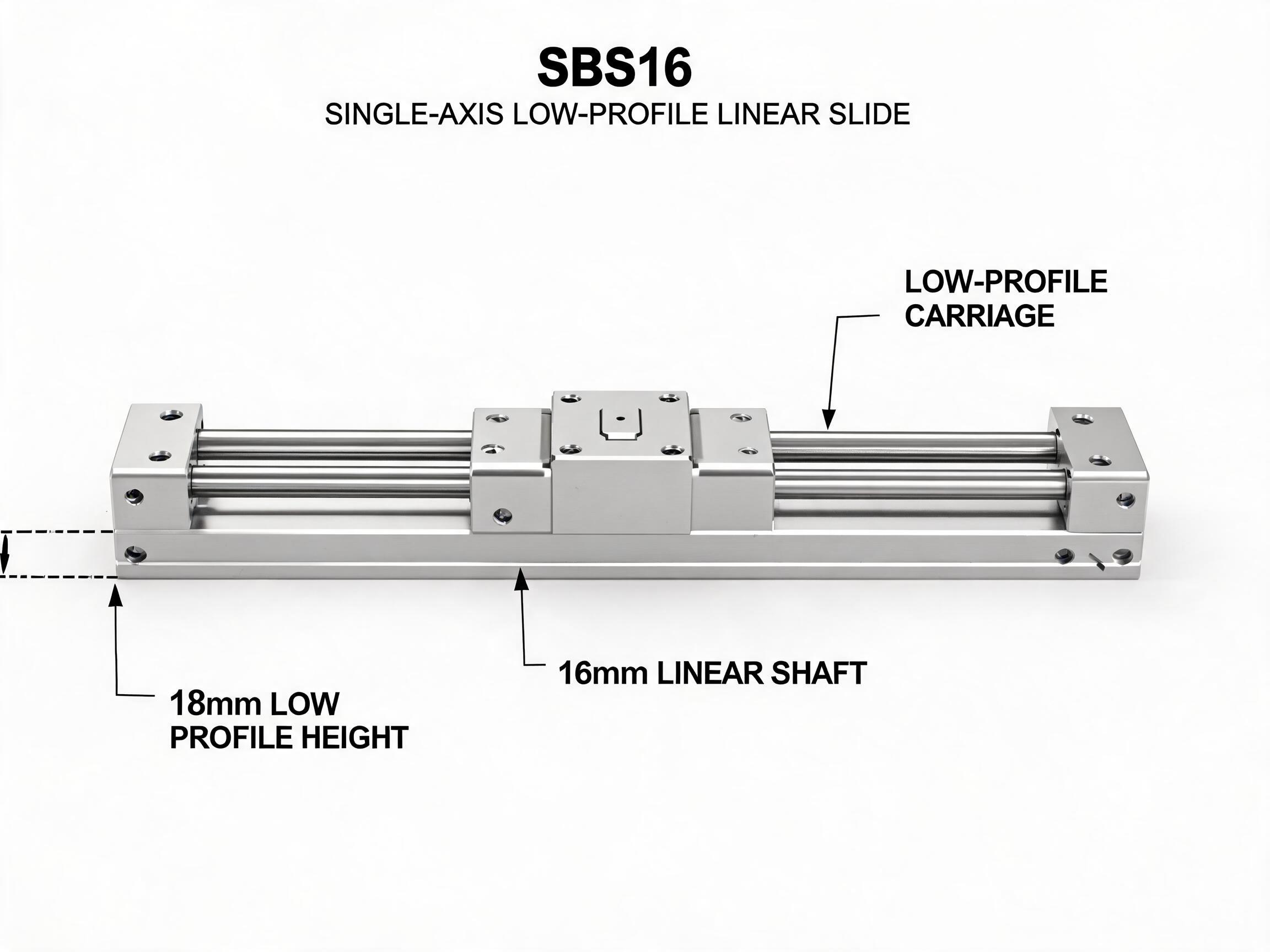
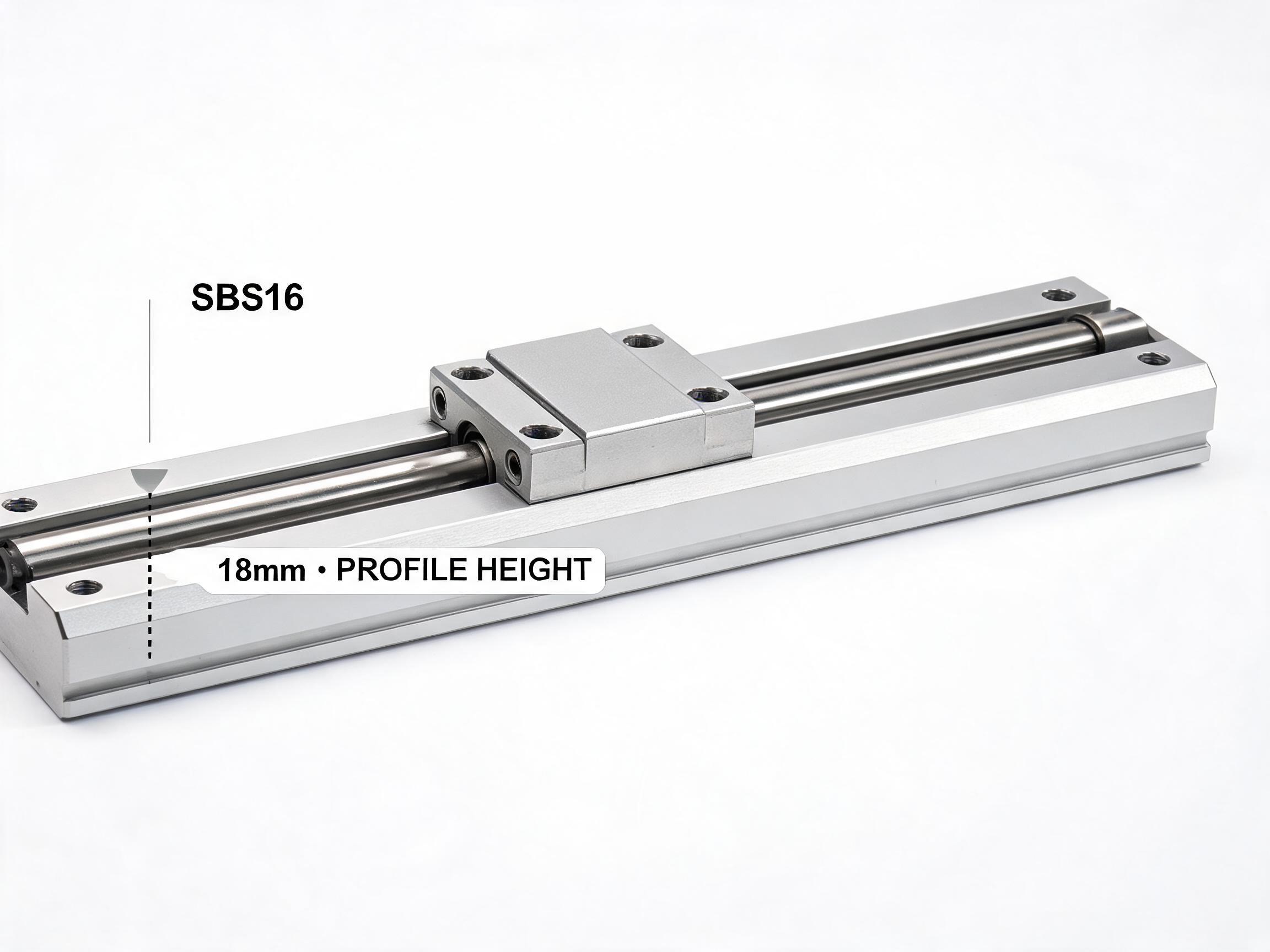
A linear axis needs one straight reference. On the SBS16 single-axis slide unit, the 6063-T5 aluminium support rail carries the GCr15 shafts hardened to HRC 58-62, and the mounting holes are on a 25 mm pitch along the rail. That pitch is the only length reference you get — the rail itself is the straight edge you locate from.
You have two workable options:
- Locate from the rail edge. Push the rail against a machined shoulder or a straight edge on the frame and hold it there while you fit the first bolts. This sets the rail line; everything else follows.
- Locate from the carriage top face. On the SBS16, the carriage top face has four M4 holes for the load. If the load interface is the critical alignment, position the carriage first and bring the rail to it.
Use one datum, not two. If you push the rail against a shoulder at one end and a different shoulder at the other, you have two datums fighting, and the rail will be forced into an S-bend. Pick the straightest available reference and keep it for the full length.
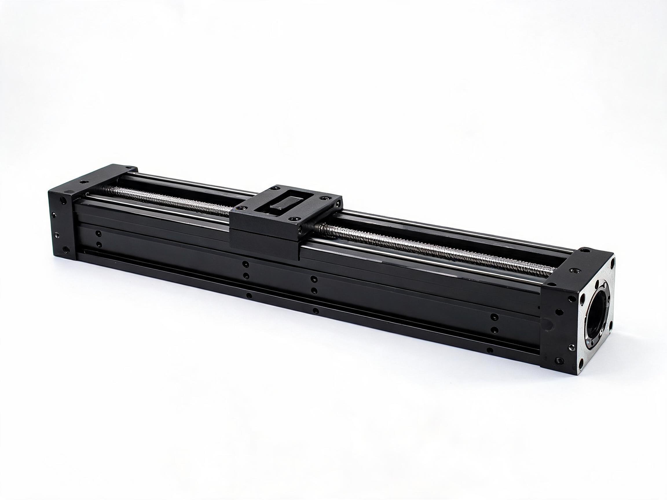
For the SKF20 module, the 2020-series T-slot profile base is the locating feature. Slide the profile into the T-slot and set the position along the slot before tightening; the SKF20 drive interface lands on the NEMA 17 or NEMA 23 motor, which is a separate alignment problem and should not be used to pull the module into line.
Tightening without distorting the rail or profile
The goal is to bring the rail or profile down onto the frame without pulling it out of line. A single bolt at one end, taken to full torque first, will tilt the rail and lift the far end off the face.
A workable sequence:
- Fit all bolts finger-tight. Confirm the rail or profile is seated on the datum face along its whole length.
- Tighten the centre bolts first, then work outwards toward both ends in pairs.
- Bring bolts to partial torque in the same pattern, then repeat to final torque in the same pattern.
- After the rail is down, re-check the carriage by hand at both ends before you fit the load.
On a guide rail such as the HGR series, the raceways are induction hardened to 58-62 HRC and the rail carries an oil groove with an oil nipple. Treat the oil nipple as a mounting feature: leave access to it after the rail is down, or you will not be able to lubricate the block without removing the rail. The hardening is in the raceway, not in the mounting face, so a rail clamped unevenly will still bend between fixings even though the raceway itself is hard.
When a second rail or second axis is added
Two parallel rails on one frame form a four-point constraint. If the second rail is set from a different datum, or if its height above the first differs, the carriage cannot sit on both. It will either lift one rail or bind along the length.
For a second rail or a second axis:
- Set both rails from the same datum edge. The first rail establishes the line; the second is set parallel to it, not to a new shoulder that may not be parallel to the first.
- Check both rails are at the same height above the frame face. The SBS16 system height is 18 mm, about 40 percent lower than the equivalent SBR16 unit. A second rail at a different height forces one side of the carriage up.
- Do not use the second rail's bolts to pull it into position. If it needs force to sit parallel, the frame or the first rail is wrong.
- For a second motorised axis, keep the two module bases parallel and do not let the driven axis load the passive axis in a way that changes the carriage preload. The SKF20 module stroke options are 100, 200, 300 and 500 mm, customisable to 1000 mm, so a long module needs the frame flat over that full length, not just at the mounting points.
The parallelism requirement on the SKF20 mounting surface is 0.02 mm. This is the one check that needs a supplier-verified measurement if you do not have a suitable instrument on site. If you cannot measure it, fit the module and check free travel by hand first; roughness at one end or the middle points at the mounting face, not the module.
Verifying free travel over the whole stroke
Move the carriage or module by hand, slowly, over the full stroke. What you are listening for and feeling for:
- Effort is even. A consistent light drag along the length is normal. A step, a tight spot, or a change in effort near one end points at a mounting problem.
- Both ends are free. Park the carriage 10-20 mm from each end stop and push it. It should move with the same light effort as the middle.
- No rocking. Try to lift or rock the carriage against the rail. A carriage that rocks has lost preload or is sitting on a twisted rail.
- Repeat after the load is fitted. Load changes the moment on the carriage; a rail that was free empty can bind under load if the frame is soft or the bolts are uneven.
Do this check before you connect the motor. If the axis is not free by hand, it will not be free under drive, and the motor will mask the friction as heat or lost steps.
FAQ
How do I set up a linear actuator without it binding?
Flat, clean mounting face first; one datum edge; centre-out tightening; then check free travel by hand over the full stroke. Binding almost always starts at the frame face or the tightening order, not inside the unit.
How do I set up a lead screw axis?
Treat the lead screw as a driven axis: align the rail or profile first, then couple the motor. Do not let the motor mounting pull the carriage into line. On the SKF20 module, the NEMA 17 or NEMA 23 motor interface is separate from the profile base, so align the base, then fit the motor.
What is linear actuator feedback?
Feedback is the position signal returned to the controller. It is generated by the drive or the encoder, not by the rail or the carriage. Mounting alignment does not create feedback, but misalignment shows up as position error when the axis stalls or slips under load.
How do I select a linear actuator for my frame?
Selection is a separate question from mounting. Match the system height, stroke and load to the frame. The SBS16 is an 18 mm system height with 5.2 kN dynamic and 8.0 kN static load, in 150, 200, 300 and 500 mm standard lengths, customisable up to 1000 mm. The SKF20 module is a motorised unit with 11.2 kN dynamic and 17.5 kN static load, 2020-series profile base, and 100, 200, 300 and 500 mm stroke options, customisable to 1000 mm.
If free travel is still rough after these checks, the next step is to measure the frame face and the parallelism of the mounting surface. That is the point where a supplier measurement is worth more than another round of tightening. Our engineers can discuss the SBS16, SKF20 and HGR mounting data against your frame drawing.